


SYSTEM SETUP:
RECEIVER ANTENNAS
Setup of receiver antennas involves first the antenna-to-
receiver interface and then antenna placement. The
simplest case is a receiver with the antenna(s) permanently
attached. The antenna is typically a quarter-wave
telescoping or possibly "rubber ducky" type. Receivers with
non-detachable antennas should be placed on an open
surface or shelf, in line-of-sight to the transmitter, for proper
operation. They are often not suitable for rack mounting
except perhaps as a single unit at the top of a rack and then
only if the antennas are mounted on the front of the
receiver or can project through the top of the rack.
A receiver with detachable antennas offers more
versatility in setup. In most cases the antennas attach to
the rear of the receiver. If the receiver is to be mounted in
a metal rack the antennas must be brought to the outside
of the rack. Some designs allow the antennas to be
moved to the front of the receiver, while others provide an
accessory panel for antenna relocation. Again, the
receiver should be mounted high enough in the rack so
that the antennas are essentially in the open.
Here are some general rules concerning setup and
use of receiver antennas:
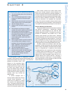
1) Maintain line-of-sight between the transmitter and
receiver antennas as much as possible, particularly for
UHF systems.
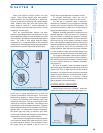
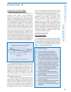
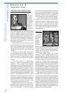
Avoid metal objects, walls, and large numbers
of people between the receiving antenna and its associated
transmitter. Ideally, this means that receiving antennas should
be in the same room as the transmitters and elevated above
the audience or other obstructions. (See Figure 4-6.)
2) Locate the receiver antenna so that it is at a
reasonable distance from the transmitter.
A minimum
distance of about 5 meters is recommended to avoid
potential intermodulation products in the receiver. The
maximum distance is not constant but is limited by
transmitter power, intervening objects, interference, and
receiver sensitivity. Ideally, it is better to have the
antenna/receiver combination closer to the transmitter
(and run a long audio cable) than to run a long antenna
cable or to transmit over excessively long distances.
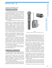
3) Use the proper type of receiver antenna.
A quarter-wave antenna can be used if it is mounted directly
to the receiver, to an antenna distribution device or to
another panel, which acts as a ground-plane. If the
antenna is to be located at a distance from the receiver, a
half-wave antenna is recommended. This type has some-
what increased sensitivity over the quarter-wave and does
not require a ground-plane. For installations requiring
more distant antenna placement or in cases of strong
interfering sources it may be necessary to use a directional
(Yagi or log-periodic) antenna suitably aimed. Telescoping
antennas should be extended to their proper length.
4) Select the correctly tuned receiver antenna(s).
Most antennas have a finite bandwidth making them
suitable for receivers operating only within a certain
frequency band. When antenna distribution systems are
used, receivers should be grouped with antennas of the
appropriate frequency band as much as possible. For the
VHF range: if the receiver frequencies span two adjacent
antenna bands, the longer (lower frequency) antennas
should be used. If the range spans all three antenna
bands, one long antenna and one short antenna should
be used (no middle length antenna). For the UHF range:
receivers should only be used with antennas of a
matching range.
5) Locate diversity receiver antennas a suitable
distance apart.
For diversity reception the minimum
separation for significant benefit is one-quarter wavelength
(about 30 cm. for VHF and about 10 cm. for UHF ). The
effect improves somewhat up to a separation of about one
wavelength. Diversity performance does not change sub-
stantially beyond this separation distance. However, in
some large area applications, overall coverage may be
improved by further separation. In these cases one or both
antennas may be located to provide a shorter average
distance to the transmitter(s) throughout the operating area.
6) Locate receiver antennas away from any suspected
sources of interference.
These include other receiver and
transmitter antennas as well as sources mentioned earlier
such as digital equipment, AC power equipment, etc.
7) Mount receiver antennas away from metal
objects.
Ideally, antennas should be in the open or else
perpendicular to metal structures such as racks, grids,
metal studs, etc. They should be at least one-quarter
wavelength from any parallel metal structure. All antennas
in a multiple system setup should be at least one-quarter
wavelength apart.
8) Orient receiver antennas properly. A non-
diversity receiver should generally have its antenna vertical.
Diversity receivers can benefit from having antennas angled 45
degrees apart. Yagi and log-periodic types should be
oriented with their transverse elements vertical.
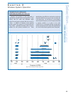
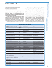
9) Use the proper antenna cable for remotely
locating receiver antennas.
A minimum length of the
appropriate low-loss cable equipped with suitable
connectors will give the best results. Refer to the chart
presented earlier. Because of increasing losses at higher
frequencies, UHF systems may require special cables.
10) Use an antenna distribution system when possible.
This will minimize the overall number of antennas and may
reduce interference problems with multiple receivers. For
two receivers a passive splitter may be used. For three or
more receivers active splitters are strongly recommended.
Verify proper antenna tuning as mentioned above. Antenna
amplifiers are not usually necessary for VHF systems but
may required for UHF systems with long cable runs.
Selection
and Operation
of Wireless Microphone Systems
42
C HAPTER 4