


A variation that is found in a few compander designs is
to divide the audio signal into two or more frequency bands.
Each band is then pre-emphasized and compressed
independently. In the receiver, de-emphasis and expansion
are applied separately to these same bands before
combining them back into a full-range audio signal. Though
more expensive, multi-band companding systems may
have a better ability to improve dynamic range and
apparent signal-to-noise ratio across the entire audio range.
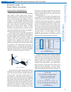
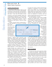
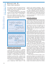
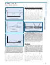
A limitation of fixed-ratio companders is that the same
amount of signal processing is applied regardless of
signal level. Dynamics processors perform compression
or expansion functions based on an evaluation of the
"average" signal level, which fluctuates continuously.
Because this process is not instantaneous, the compander
action is not completely transparent. With good design,
audible "artifacts" are minimal but may become more
apparent when the signal level is extremely low. This
accounts for occasional "modulation" noise or background
noise intrusion that accompanies low-level audio signals,
especially when the radio signal itself is weak or noisy.
The performance of full-band companding systems can
be improved by first optimizing the measurement of the
average signal level. A "true RMS" detector is preferred,
since this technique most closely tracks the amplitude of a
full range audio signal, regardless of frequency response.
Further improvement can be realized by using level-
dependent companding. For low level audio signals, little
or no processing is applied so there are no audible effects.
As the audio signal level increases, processing levels are
increased, so that potentially audible artifacts are masked.
Implementation of this scheme requires a high
performance VCA and close tolerance in the audio
sections of transmitters and receivers.
In many transmitters, an additional process called limiting
is applied to the audio signal. This is to prevent overload and
distortion in subsequent audio stages or to prevent
"overmodulation" (excessive frequency deviation) of the radio
signal. The "limiter" automatically prevents the audio signal
level from exceeding some preset maximum level and is
usually applied after pre-emphasis and companding.
TRANSMITTER: RADIO CIRCUITRY
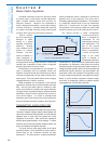
After processing, the audio signal is sent to a voltage-
controlled oscillator (VCO). This is the section that actually
converts the audio signal to a radio signal by the technique
called frequency modulation (FM). The (relatively) low
frequency audio signal controls a high frequency oscillator
to produce a radio signal whose frequency "modulates" or
varies in direct proportion to the audio signal.
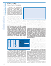
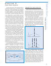
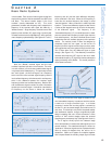
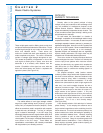
The maximum value of modulation is called the
deviation and is specified in kilohertz (KHz). The amount of
deviation produced by the audio signal is a function of the
design of the transmitter. Systems with deviation greater
than the modulating frequency are called wideband, while
systems with deviation less than the modulating frequency
are called narrow band. Most wireless microphone
transmitters fall into the upper end of the narrow band
category. (See Figures 2-6 a & b.)
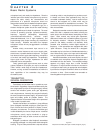
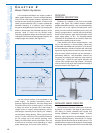
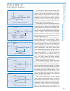
The "base" or unmodulated frequency of the oscillator for
a single frequency system is fixed. By design, the
frequency of the signal from the VCO (for a conventional,
crystal-controlled transmitter) is much lower than the desired
output frequency of the transmitter. In order to achieve a given
transmitter frequency the output from the VCO is put through
a series of frequency multiplier stages. These multipliers are
usually a combination of doublers, triplers, or even quadruplers.
For example, a transmitter that employs two triplers (for a 9x
multiplication) would use a VCO with a base frequency of 20
MHz to achieve a 180 MHz transmitted frequency. The
multipliers also function as amplifiers so that the output signal
is at the desired power level as well. (See Figure 2-7.)
11
Selection
and Operation
of Wireless Microphone Systems
C HAPTER 2
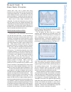
Basic Radio Systems
Figure 2-5: compander (2:1, fixed rate)
Figure 2-6b: modulated FM signal spectrum
Figure 2-6a: unmodulated FM signal spectrum