


required by the microphone (usually between 11 and 52
volts DC). If less than the minimum is available, the
condenser microphone performance may be
compromised with less headroom or more distortion. This
is not a concern with dynamic microphones (which do not
require power) or with condenser microphones powered
by an internal battery.
The bodypack transmitter presents the greatest range
of possible interfaces. The simplest arrangement is the
hard-wired lavaliere or headset microphone. Again, it can
usually be assumed that this design already provides the
optimum interface for the components provided. If various
hardwired microphone choices are offered, the selection
should be based on the intended application.
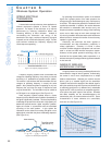
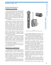
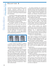
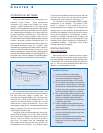
Most bodypack transmitters are equipped with an
input connector to allow the use of a variety of
microphones and other input sources. (See Figure 4-2.)
Microphones and input cables supplied by a manufacturer
with a given wireless microphone system can be assumed
to be compatible with that system. However, they may not
be directly compatible with wireless microphone systems
from other manufacturers. At a minimum, a connector
change is often required. In many cases, additional
circuitry or modifications to components will be necessary.
A few combinations simply will not work.
In order to determine the suitability of a particular
microphone for use with a particular transmitter it is first
necessary to determine the connector type(s) involved.
Connectors include eighth-inch and quarter-inch phone
jacks as well as a variety of multi-pin designs.
Next, the wiring of the microphone connector and the
wiring of the transmitter connector must be compared.
Unfortunately, there is no standard input connector, and further,
the wiring scheme of the same connector may
differ from one manufacturer to another. A quarter-inch input
jack is usually wired unbalanced with the audio signal at the tip
and shield on the sleeve. The typical multi-pin input on a
body-pack transmitter has at least one pin for the audio signal
and one pin for shield or ground. There may be other pins to
provide "bias" (a DC voltage for a condenser microphone
element) or to provide an alternate input impedance. Some
transmitters have additional pins to accept audio signals at
different levels or to provide a combination audio + bias for
certain condenser elements.
The electrical characteristics of the microphone and
transmitter should then be compared: the output level of the
microphone should be within the acceptable input level
range of the transmitter and the output impedance of the
microphone should be less than the input impedance of the
transmitter. In addition, the input configuration of most
bodypack units is unbalanced. Microphones intended for
use with wireless are also invariably unbalanced, though a
balanced output dynamic microphone can usually be
accommodated with an adapter cable.
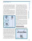
If the microphone has a condenser element and does
not have its own power source then the transmitter must
supply the required bias voltage. Most transmitters
provide about 5 VDC, suitable for a typical electret
condenser element, though some elements may require
as much as 9 VDC. In this case, it is sometimes possible
to modify the transmitter to provide the higher voltage.
Many condenser elements and associated
transmitters use a two-conductor-plus-shield hookup in
which the audio is carried on one conductor and the bias
voltage on the other. A few condenser elements and some
transmitters use a single-conductor-plus-shield
arrangement in which the audio and bias voltage are
carried on the same conductor. Interfacing a microphone
of one scheme with a transmitter of the other may require
modification of one or both components.
In general, for non-standard combinations, it is best to
directly contact the manufacturer of the wireless microphone
system and/or the manufacturer of the microphone to
determine the compatibility of the desired components. They
can provide the relevant specifications and can usually
describe any limitations or necessary modifications.
Non-microphone sources include electronic musical
instruments and possibly outputs from sound systems and
playback devices. Though none of these sources require
bias or phantom power their interface presents a much
wider range of level and impedance than a typical
microphone source.
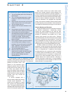
Musical instruments such as electric guitars and basses
can have output levels from a few millivolts (microphone
level) for instruments with passive pickups to a few volts
(line level) for those with active pickups. The transmitter
must be capable of handling this dynamic range to avoid
overmodulation or distortion.
Ordinary (passive) magnetic instrument pickups have
a high output impedance and require a transmitter input
impedance of about 1 Megohm to insure proper
frequency response. Active (powered) pickups have fairly
low output impedance and will work with almost any
transmitter input impedance of 20,000 ohms or greater.
Piezoelectric pickups have very high output impedance
and require a 1-5 Megohm transmitter input impedance to
avoid loss of low frequencies.
Selection
and Operation
of Wireless Microphone Systems
38
C HAPTER 4
Figure 4-2: examples of input connectors
1/4”
mini XLR Lemo