


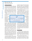
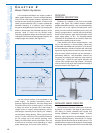
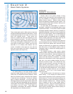

A few tuneable transmitters use multiple crystals to
obtain multiple frequencies. However, the base frequency
of the VCO for most tuneable systems is adjustable by a
technique known as frequency synthesis. A control circuit
called a phase-locked-loop (PLL) is used to calibrate the
transmitter frequency to a reference "clock" frequency
through an adjustable frequency divider. By changing the
divider in discrete steps, the transmitter frequency can be
precisely varied or tuned over the desired range.
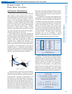
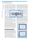
Frequency-synthesized designs allow the audio signal to
modulate the VCO directly at the transmitter frequency. No
multiplier stages are required. (See Figure 2-8.)
The last internal element of the transmitter is the
power supply. For portable transmitters, power is
generally supplied by batteries. Since the voltage level
of batteries falls as they are discharged, it is necessary
to design the device to operate over a wide range of
voltage and/or to employ voltage-regulating circuitry.
Most designs, especially those requiring a 9 V battery,
use the battery voltage directly. Others, typically those
using 1.5 V cells, have DC-to-DC converters that boost
the low voltage up to the desired operating value.
Battery life varies widely among transmitters, from just
a few hours up to twenty hours, depending on output
power, battery type, and overall circuit efficiency.
RECEIVER:
GENERAL DESCRIPTION
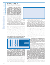
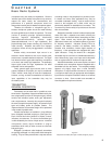
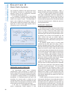
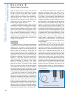
Receivers are available in both fixed and portable
designs. (See Figure 2-9.) Portable receivers resemble
portable transmitters externally: they are characterized by
small size, one or two outputs (microphone/line, head-
phone), minimal controls and indicators (power, level), and
(usually) a single antenna. Internally they are functionally
similar to fixed receivers, again with the exception of the
power supply (battery vs. AC). The important features
ofreceivers will be presented in the context of fixed units,
which exhibit a greater range of choices.
Fixed receivers offer various outward features: units
may be free standing or rack-mountable; outputs may
include balanced/unbalanced microphone or line level as
well as headphones; indicators for power and audio/radio
signal level may be present; controls for power and output
level are usually offered; antennas may be removable or
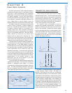
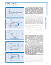
permanently attached. Like transmitters, receivers can
vary greatly in packaging, but inside they must achieve a
common goal: receive the radio signal efficiently and
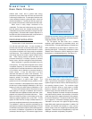
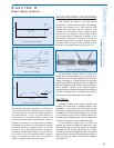
convert it into a suitable audio signal output. Once again
it will be useful to look at the main functional elements of
the typical receiver. (See Figure 2-10.)
RECEIVER: RADIO CIRCUITRY
The first section of receiver circuitry is the "front end."
Its function is to provide a first stage of radio frequency
(RF) filtering to prevent unwanted radio signals from
causing interference in subsequent stages. It should
effectively reject signals that are substantially above or
below the operating frequency of the receiver. For a single
frequency receiver the front end can be fairly narrow. For a
tuneable receiver it must be wide enough to accommodate
the desired range of frequencies if the front end filter itself
Selection
and Operation
of Wireless Microphone Systems
12
C HAPTER 2
Basic Radio Systems
Figure 2-7: crystal-controlled transmitter
Figure 2-8: frequency-synthesized transmitter
Figure 2-9:
receiver examples
fixed
portable