


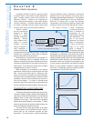
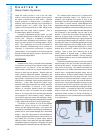
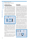

output will usually consist of a mix of the two audio
sections. In the case of loss of reception at one antenna,
the output is chosen from the other section. Excellent
dropout protection is obtained with no possibility of
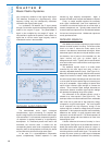
switching noise since the diversity circuit is essentially an
intelligent panpot, not a switch. (See Figure 2-24.)
Signal-to-noise is improved by up to 3 dB. Range can be
greater than with single antenna systems. Cost is
somewhat higher, setup is convenient.
A properly implemented diversity system can yield
measurable improvements in reliability, range, and signal-
to-noise ratio. Although a comparable non-diversity
system will perform adequately most of the time in typical
setups, the extra insurance of a diversity system is worth-
while. This is particularly true if the RF environment is
severe (multipath), troubleshooting time is minimal (no
rehearsal), or dropout-free performance is required
(ideally always). The price difference is small enough that
diversity receivers are typically chosen in all but the most
budget-conscious applications.
ANTENNAS
In addition to the circuitry contained inside transmitters
and receivers, one critical circuitry element is often located
outside the unit: the antenna. In fact, the design and
implementation of antennas is at least as important as the
devices to which they are attached. Although there are
certain practical differences between transmitting and
receiving antennas there are some considerations that
apply to both. In particular, the size of antennas is directly
proportional to wavelength (and inversely proportional to
frequency). Lower radio frequencies require larger
antennas, while higher frequencies use smaller antennas.
Another characteristic of antennas is their relative
efficiency at converting electrical power into radiated
power and vice versa. An increase of 6 dB in radiated
power, or an increase of 6 dB in received signal strength
can correspond to a 50% increase in range. Likewise, a
loss of 6 dB in signal may result in 50% decrease in range.
Though these are best (and worst) case predictions, the trend
is clear: greater antenna efficiency can give greater range.
The function of an antenna is to act as the interface
between the internal circuitry of the transmitter (or
receiver) and the external radio signal. In the case of the
transmitter, it must radiate the desired signal as efficiently as
possible, that is, at the desired strength and in the desired
direction. Since the output power of most transmitters is
limited by regulatory agencies to some maximum level, and
since battery life is a function of power output, antenna
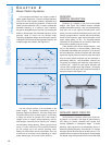
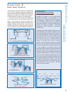
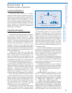
efficiency is critical. At the same time, size and portability of
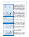
transmitters is usually very important. This results in only a few
suitable designs for transmitter antennas. (See Figure 2-25.)
The smallest simple antenna that is consistent with
reasonable transmitter output is an antenna that is
physically (and electrically) one quarter as long as the
wavelength of the radio wave frequency being transmitted.
This is called a "1/4 wave" antenna. It takes different forms
depending on the type of transmitter being used. For some
bodypack transmitters, the antenna is a trailing wire cut to an
appropriate length. In other designs the cable that attaches
the microphone to the transmitter may be used as the
antenna. In either case, the antenna must be allowed to
extend to its proper length for maximum efficiency. The
effective bandwidth of this antenna type is great enough that
only about three different lengths are required to cover the
high-band VHF range. For transmitter applications requiring
even smaller antenna size a short "rubber duckie" antenna
is sometimes used. This type is still (electrically) a 1/4 wave
antenna, but it is wound in a helical coil to yield a shorter
package. There is some loss in efficiency due to the
smaller "aperture" or physical length. In addition, these
antennas have a narrower bandwidth. This may require up
to six different lengths to cover the entire high-band VHF
range for example.
Handheld transmitters generally conceal the antenna
inside the body of the unit, or use the outer metal parts of
the case as the antenna. In either design, the antenna is
rarely a true 1/4 wave long. This results in somewhat less
radiated power for a handheld transmitter with an internal
antenna than a comparable bodypack design with an
external antenna. However, antenna output is somewhat
reduced when placed close to the body of the user. Since
the antenna of a hand-held transmitter is usually at some
distance from the body, though, the practical difference
may be small. Plug-on type transmitters normally use the
microphone body and the transmitter case itself as the
antenna, though some manufacturers models have used an
external antenna. In practice the typical VHF transmitter
antenna is less than 10% efficient. UHF types may be
significantly better because the shorter wavelength of
these frequencies is more consistent with the requirement
for a small antenna.
Selection
and Operation
of Wireless Microphone Systems
18
C HAPTER 2
Basic Radio Systems
Figure 2-25: transmitter antenna examples
trailing wire
internal
rubber-duckie