


only of frequency variations of the original input signal.
This effectively eliminates the (high-frequency) carrier
frequency leaving only the low-frequency modulation
information (the original audio signal).
In a quadrature FM detector the IF signal passes
through a circuit which introduces a 90 degree phase shift
relative to the original IF signal. The phase-shifted IF
signal is then multiplied by the straight IF signal. A
low-pass filter is applied to the product, which results in a
signal that is now the audio signal originally used to
modulate the carrier in the transmitter.
RECEIVER: A
UDIO CIRCUITRY
The demodulated audio signal undergoes
complementary signal processing to complete the
dynamic range recovery and noise reduction action begun
in the transmitter. For conventional compander systems, a
1:2 expansion is applied, followed by a high-frequency
de-emphasis. If a multi-band process was used in the
transmitter, the received audio is divided into the
corresponding bands, each band is expanded, the high
frequency band is de-emphasized, and finally the bands
are recombined to yield the full-range audio signal.
In the case of a signal-dependent compression
system, complementary variable expansion is used
followed by high frequency de-emphasis. Again, a
precision VCA with a true-rms audio level detector is required.
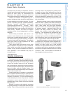
Finally, an output amplifier supplies the necessary
audio signal characteristics (level and impedance) for
connection to an external device such as a mixer input, a
recorder, headphones, etc. Typically, better receivers will
include a balanced output that can be switched between
line level and microphone level. Unbalanced outputs are
usually provided as well.
RECEIVER: SQUELCH
One additional circuit that is important to proper receiver
behavior is called "squelch" or muting. The function of this
circuit is to mute or silence the audio output of the
receiver in the absence of the desired radio signal. When
the desired signal is lost (due to multi-path dropout, exces-
sive distance, loss of power to the transmitter, etc.) the
"open" receiver may pick up another signal or
background radio "noise." Typically, this is heard as "white"
noise and is often much louder than the audio signal from
the desired source.
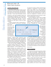
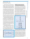
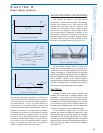
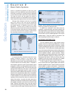
The traditional squelch circuit is an audio switch
controlled by the radio signal level using a fixed or
manually adjustable threshold (level). (See Figure 2-14.)
When the received signal strength falls below this level the
output of the receiver is muted. Ideally, the squelch level
should be set just above the background radio noise level
or at the point where the desired signal is becoming too
noisy to be acceptable. Higher settings of squelch level
require higher received signal strength to unmute the
receiver. Since received signal strength decreases as
transmission distance increases, higher squelch settings
will decrease the operating range of the system.
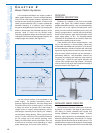
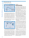
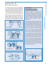
One refinement of the standard squelch circuit is
referred to as "noise squelch." (See Figure 2-15.) This
technique relies on the fact that the audio from undesirable
radio noise has a great deal of high frequency energy
compared to a typical audio signal. The noise squelch
circuit compares the high frequency energy of the
received signal to a reference voltage set by the squelch
adjustment. In this system the squelch control essentially
determines the "quality" of signal (signal-to-noise ratio)
required to unmute the receiver. This allows operation at
lower squelch settings with less likelihood of noise if the
desired signal is lost.
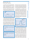
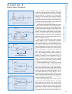
A further refinement is known as "tone-key" or "tone-
code" squelch. (See Figure 2-16.) It enables the receiver to
identify the desired radio signal by means of a supra- or
sub-audible tone that is generated in the transmitter and
sent along with the normal audio signal. The receiver will
unmute only when it picks up a radio signal of adequate
strength and also detects the presence of the tone-key.
Selection
and Operation
of Wireless Microphone Systems
14
C HAPTER 2
Basic Radio Systems
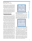
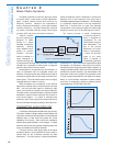
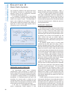
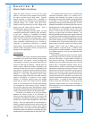
Figure 2-13a: double conversion, crystal-controlled receiver
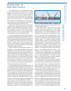
Figure 2-13b: double conversion, frequency-synthesized receiver