


received signal by an amount equal to the intermediate
frequency (IF). Specifically, the operating frequency is
above the local oscillator frequency by an interval equal to
the IF. When these two frequencies are applied to the mixer
section (a non-linear circuit) one of the output frequencies of
the mixer is this difference frequency (the IF), which is the
tuned frequency of the subsequent IF stage filters.
If the frequency of a second signal is at the same
interval below the local oscillator frequency, the difference
between this second frequency and the LO frequency
would again be equal to the intermediate frequency (IF).
The mixer stage does not discriminate between "positive"
or "negative" frequency differences. If this second (lower)
frequency enters the mixer stage, it will result in another
(difference) signal getting to the IF stages and causing
possible interference. This lower frequency is called the
"image" of the original frequency. Again, assuming an IF of
10.7 MHz, a receiver tuned to 200.7 MHz would have its LO
at 190.0 MHz. A signal from another transmitter at 179.3
MHz would appear as an image frequency since it is 10.7
MHz below the LO frequency or 21.4 MHz below the
operating frequency.
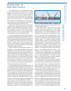
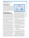
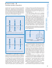
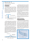
The image frequency differs from the operating
frequency by an amount equal to two times the intermediate
frequency (2 x IF). (See Figures 3-9 a & b.) The image
frequency will be below the operating frequency for a high-side
injection receiver and above the operating frequency for a
low-side injection receiver. Thus the image frequency for the
typical single conversion receiver is at least 20 MHz away from
the operating frequency. Double conversion receivers, which
have a relatively high first IF (50 MHz typical), have image
frequencies which are even farther (>100 MHz typical) away
from the operating frequency. In most cases, the front end of
the receiver should be able to reject an image frequency
unless it is extremely strong. Nevertheless, it is recommended
that operating frequencies be chosen to be at least 250 KHz
from any image frequency.
The last internal frequency issue concerns the VCO in
crystal controlled transmitters. Recall that the actual VCO
frequency is a relatively low radio frequency that is
multiplied to obtain the final transmitter frequency. A small
amount of the original crystal frequency remains after each
multiplier stage. Thus the output signal includes not only
the final operating frequency but also low-level "spurs" or
spurious emissions due to the multipliers. These spurs
occur above and below the operating frequency at
intervals equal to "harmonics" (multiples) of the original
crystal frequency.
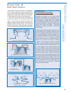
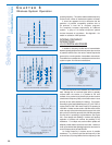
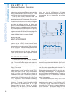
For example, assuming a 9 x multiplier, a 180 MHz
transmitter would have a 20 MHz crystal frequency. This
would produce spurs at 160 MHz and 200 MHz, 140 MHz
and 220 MHz, etc. Good transmitter design will minimize
the amplitude of such crystal harmonics but, again,
additional receivers should be chosen to avoid these
frequencies by at least 250 KHz. (See Figure 3-10.)
Frequency-synthesized transmitters do not produce
spurious emissions of this type because they do not employ
27
Selection
and Operation
of Wireless Microphone Systems
C HAPTER 3
Wireless System Operation
Figure 3-9a: image frequency interference (low-side injection)
Figure 3-9b: image frequency interference (high-side injection)
Figure 3-10: crystal harmonics