


Removal and Replacement Procedures
Maintenance and Service Guide 5–37
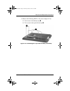
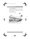
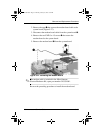
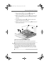
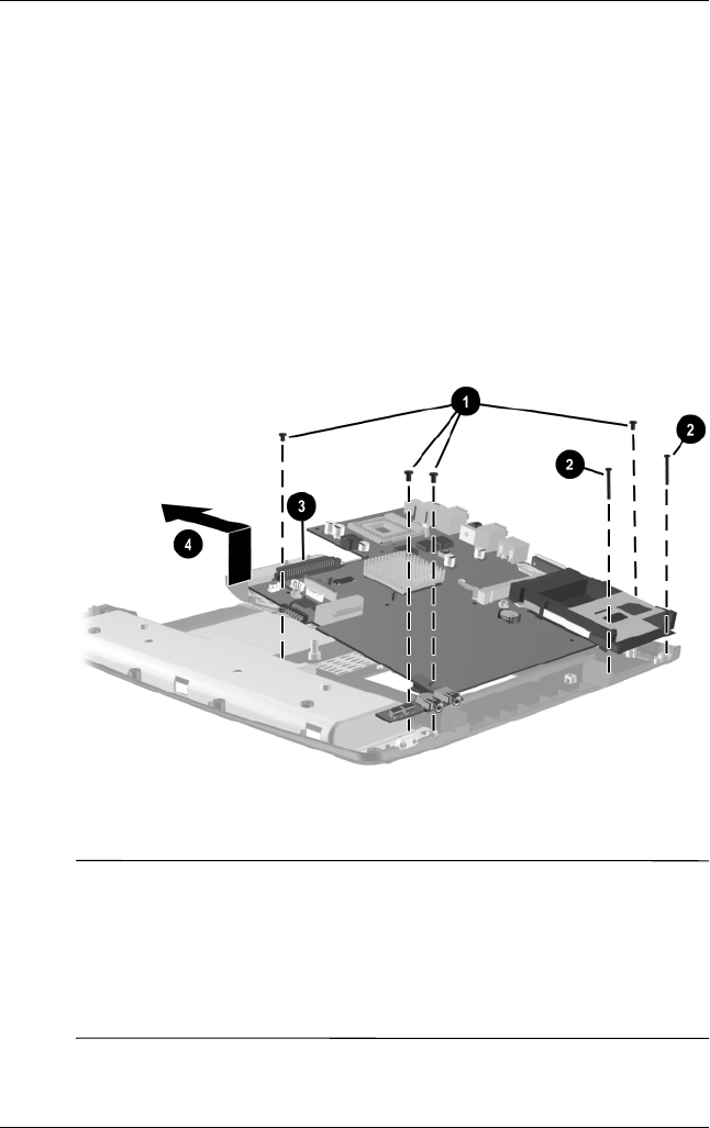
3. Remove the four PM2.5 × 4.0 screws 1 that secure the
system board to the base enclosure (Figure 5-28).
4. Remove the two PM2.0 × 13.0 screws 2 on each side of the
PC Card assembly that secure the system board to the base
enclosure.
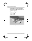
5. Use the hard drive connector 3 to lift the left side of the
system board until it rests at an angle.
6. Slide the system board to the left at an angle 4 and remove it
from the base enclosure.
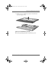
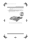
Figure 5-28. Removing the System Board
Reverse the preceding procedure to install the system board.
✎
When the system board is removed, the heat sink mounting
bracket may be loose in the base enclosure. Make sure this
bracket is aligned correctly when installing the heat sink on
the system board. The heat sink mounting bracket is included
in the Miscellaneous Plastics/Hardware Kit, spare part number
310359-001.
307503-002.book Page 37 Thursday, January 30, 2003 1:04 PM