


Removal and Replacement Procedures
Maintenance and Service Guide 5–3
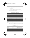
Section Description # of Screws Removed
5.3
(Continued)
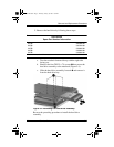
Hard drive 4 to remove hard drive
4 to separate hard drive
from hard drive
bracket
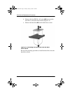
5.4 Notebook feet 0
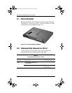
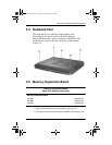
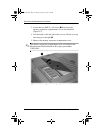
5.5 Memory expansion board 2 loosened
5.6 Optical drive 1
5.7 LED switch cover 2
5.8 Keyboard 1
5.9 Heat sink 5 loosened
5.10 Fan 3
5.11 Processor 0
5.12 Display assembly 4
5.13 Top cover 17
5.14 1394 board 1
5.15 Modem board 2
5.16 System board 6
5.17 RTC battery 0
Table 5-1
Disassembly Sequence Chart
(Continued)
307503-002.book Page 3 Thursday, January 30, 2003 1:04 PM