


5 DRX9575Rz 6 DRX9575Rz DRX9575Rz 7
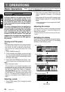
4. NOMENCLATURE
Note:
• Be sure to read this chapter referring to the front diagrams of chapter “3. CONTROLS” on page 5 (unfold).
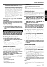
3.
CONTROLS / LES COMMANDES / CONTROLES
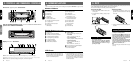
Source unit / Appareil pilote / Unidad fuente
Note: Be sure to unfold this page and refer to the front diagrams as you read each chapter.
Remarque: Veuillez déplier cette page et vous référer aux schémas quand vous lisez chaque chapitre.
Nota: Cuando lea los capítulos, despliegue esta página y consulte los diagramas.
5. DCP
Display / Afficheur / Visualizador
With the SLOPING CONSOLE opened / Ouvrez la CONSOLE RABATTABLE /
Apertura de la CONSOLA INCLINABLE
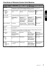
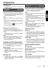
Names of Buttons
1 Release button
2 SEARCH button
3 Rotary knob
4 BAND button
TOP button
5 POWER button
FUNC (function) button
6 TA (traffic announcement) button
7 A (angle) button
8 Z-EHCR (z-enhancer) button
9 Eject button
OPEN button
! DISC IN indicator
" DISP (display) button
# S (shift) button
$ Preset buttons (1 to 6)
Direct buttons (1 to 6)
% A-M (audio mode) button
LOUD (loudness) button
& ADJ (adjust) button
( ENT (enter) button
Play/pause button
) TITLE button
~ CD insertion slot
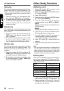
Display Items
(Function mode)
1 Function icon
2 Z-EHCR (z-enhancer) indication
3 TA (traffic announcement) indication
4 TP (traffic programe) indication
5 PTY (programe type) indication
6 ST (stereo) indication
7 LD (loudness) indication
8 MANU (manual) indication
9
• in Radio Mode
Band, programe type, frequency, etc.
• in CD Mode
Truck no., play time, user title, etc.
• in CD Changer Mode
Truck no., play time, user title, CD-TEXT, etc.
• in MD Changer Mode
Truck no., play time, MD title, etc.
• in TV Mode
Band, channel no., user title, etc.
! P.ch (preset channel) or SUB indication
" Preset channel indication
Sub menu indication
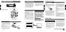
The control panel can be detached to prevent theft. When detaching the control panel, store it in the
DCP (DETACHABLE CONTROL PANEL) case to prevent scratches.
We recommend taking the DCP with you when leaving the car.
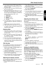
Attaching the DCP
1. Insert the DCP so that the A section on the
right side of the DCP catches on the hook B
on the unit.
2. Press the left side of the DCP carefully to fit
it in place.
CAUTION
• The DCP can easily be damaged by shocks.
After removing it, be careful not to drop it
or subject it to strong shocks.
• If the Release button
11
11
1 is pressed and the
DCP is not locked into place, it may fall out
from vibration of the car. This can break the
DCP, so after removing it, either install it on
the unit or put it in its DCP case.
• The connector connecting the unit and the
DCP is an extremely important part. Be care-
ful not to damage it by pressing on it with
fingernails, screwdrivers, etc.
Note:
• If the DCP is dirty, wipe off the dirt with a soft, dry
cloth only.
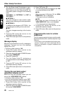
Removing the DCP
1. With the SLOPING CONSOLE closed, turn
off the power.
2. Press the Release button 1 deeply to open
the DCP.
3. Pull the DCP toward you and remove it.
CAUTION
• Always close the SLOPING CONSOLE be-
fore removing the DCP.
• If you remove the DCP with the SLOPING
CONSOLE open, the SLOPING CONSOLE
closes immediately. Be careful not to get
your fingers caught.
DCP
LCD Screen
1. In extreme cold, the screen movement may
slow down and the screen may darken, but
this is normal. The screen will recover when
it returns to normal temperature.
2. The colors displayed on the LCD screen vary
with the heat of this unit and the tempera-
ture in the car. This is a characteristic of LCDs
and is normal. The display colors return to
normal when the LCD screen returns to
normal temperature.
¥