


3133501
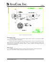
SSPA Mounting Considerations
The AnaSat
®
SSPA must be mounted such that:
1. Sufficient support is afforded the Block Up-Converter to minimize the effects of antenna sway
in strong winds.
2. Air movement is possible across the heat sink fins. Ideally, the fins should be aligned
vertically, but this is not required.
NOTE: The length (and associated RF losses) of the interconnecting cables must be considered
when determining the location of the AnaSat
®
SSPA.
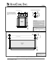
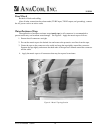
SSPA Mounting
The AnaSat
®
SSPA is designed for mounting in any position.
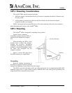
Figure 2 shows a common
installation example where the SSPA is
mounted on the antenna feed support
arm.
When mounting the SSPA, allow
enough room to adjust the antenna’s
azimuth and elevation. Throughout
installation and during any polarization,
azimuth, or elevation adjustment, ensure
the cables and waveguide are not
crimped or pinched.
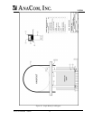
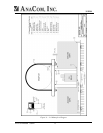
Figure 3 on the next page shows
the SSPA mounting for single thread.
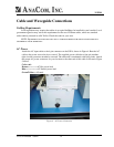
Grounding
Electrical bonding (grounding) of
the SSPA is required to prevent possible
damage from lightning or other induced electrical surges.
Figure 2 - SSPA
The SSPA is provided with both an M3, and a #8 ground point. It is recommended that 000 AWG
minimum copper wire or copper braid be used to bond this unit to the earth ground (grounding rod)
using the most direct (shortest) route possible.
ANACOM AnaSat
®
SSPA 10