


CONTROLS AND DISPLAYS
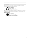
PIN ASSIGNMENT
The pin assignments of all of the XLR-type male analog outputs, the XLR-type male digital
output, and XLR-type female digital inputs are as follows:
Pin 1: Signal ground
Pin 2: Signal + (non-inverting) Pin
3: Signal - (inverting)
Connector ground lug: chassis ground
Refer to the owner's manual for the other components in your audio system to verify that the XLR
pin assignments of its input connectors correspond to the CD 500 Professional Version. If they
are different, wire the XLR cable so that the appropriate XLR output pin connects to the
equivalent XLR input pin.
Pin 1: Signal ground
Pin 2: Signal + (non-inverting) Pin
3: Signal - (inverting)
Connector ground lug: chassis ground
11