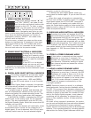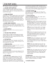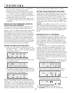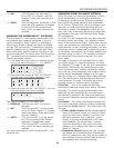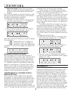
SP2 PREAMP/PROCESSOR
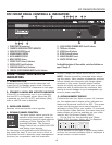
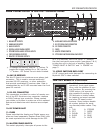
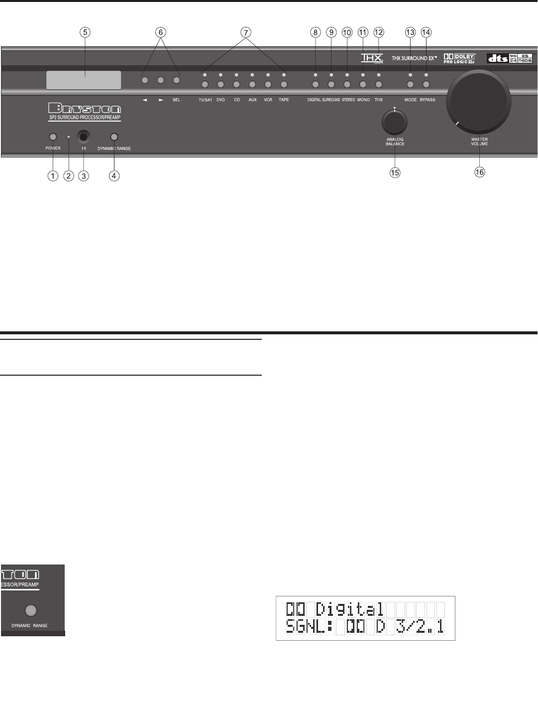
SP2 FRONT PANEL CONTROLS & INDICATORS
1: POWER SWITCH (momentary)
2: STANDBY & INFRA-RED ACTIVITY INDICATOR
3: INFRA-RED RECIEVER (sensor)
4: DYNAMIC RANGE CONTROL
5: ALPHA-NUMERIC DISPLAY
6: MENU CONTROL Buttons
7: SOURCE SELECT Buttons & Indicators
8: DIGITAL MODE Switch & Indicator
9: SURROUND MODE Switch & Indicator
10: STEREO & STEREO DOWNMIX MODE Switch & Indicator
11: MONO & MONO DOWNMIX MODE Switch & Indicator
12: THX Button & Indicator
13: MODE Button & Indicator
14: BYPASS Button & Indicator
15: ANALOG BALANCE Control
16: MASTER VOLUME Control
See detailed descriptions of these switches, controls and indicators on
pages 3 through 7)
4
FRONT PANEL CONTROLS &
INDICATORS
1: POwER BUTTON
Pressing this push button switch takes the unit
in and out of its Standby power mode. See also
”POWER INLET & SWITCH” elsewhere on this page.
2: STANDBY & INFRA-RED ACTIVITY INDICATOR
If this LED is continuously red, it is an indication
that the SP2 is in Standby mode. When the SP2
is powered up, the LED is OFF, and flashes (Red)
when a valid IR code is detected.
3: INFRA-RED SENSOR
Receives infra-red remote control signals
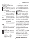
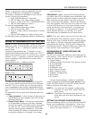
4: DYNAMIC RANGE CONTROL
This push button switch permits the
selection of three dymanic range (or
compression) levels of signal sources
producing a Dolby Digital or DTS
encoded bitstream. The Dynamic
Range Control has no effect with PCM
and Analog input signals.
For the majority of applications the MEDIUM set-
ting should be used. If you wish to turn off all of
the software’s built-in dynamic range management
functions (no compression and thus maximum
dynamic range) the switch can be set to “FULL”.
NOTE: Caution should be exercised when choos-
ing this option. Many smaller loudspeaker systems
cannot handle the extremely wide range signals
produced in this mode. Overall system volume
should be initially set quite low until you or your
dealer are able to determine the maximum safe
setting to avoid damage to your loudspeaker sys-
tems or power amplifiers.
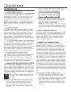
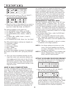
5: ALPHA-NUMERIC DISPLAY
Contains the two line, black on green 16 character
per line alphanumeric display which indicates the
status and functional mode of the SP2. This screen
is also used during the menu-setup function for
calibration of the SP2 to your system. If connected
to the Bryston Video Switcher, the menu-setup and
status display will also be available on your video
monitor with On-Screen Display (OSD).
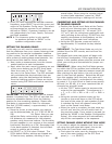
On the first line, the decoding type [Dolby
Digital, DTS, Pro-Logic, Music, etc.] is displayed.
On the second line the type of signal being detect-
ed from the currently selected input is displayed. A
sample screen is shown below:


