INTRODUCTION
Congratulations on your purchase of the Bryston
SP2 pre-amplifier/processor. This product will pro-
vide you with the finest available signal control and
DSP audio processing available. Like all Bryston
products the SP2 has been carefully designed and
engineered to deliver a lifetime of enjoyment.
The SP2 offers both pre-amplifier and digi-
tal decoding functions, and it is very important
that you thoroughly read this manual BEFORE you
install and use the SP2.
UNPACKING
Your SP2 was carefully packed at the factory to
protect against any damage in shipping and han-
dling. Carefully examine the packing and the unit
for any signs of external damage or impact and
report those to your dealer or Bryston prior to
using the unit.
Bryston advises that you keep all packaging
in the event that the unit may have to be returned
for service.
ACCESSORIES
In the carton you should have found the following
accessories in addition to the SP2:
1 Bryston SP2 Instruction Manual
1 IEC standard power cord
1 SP2 Infrared Remote Control unit with
backlight and battery installed
SAFETY
It is VERY IMPORTANT that you read and complete-
ly understand the safety instructions and warning
on page one of this manual before installing or con-
necting the SP2 to any electrical power source.
NEw FEATURES
• New “C” series cosmetics
• RS-232 software updates
• DSP firmware updates via SPDIF
• New Texas Instruments Aureus Audio DSP chip
• Seven times greater processing power
• DTS 96/24 5.1 surround decoding
• Dolby 96/24 two channel surround PLIIx
decoding
• Four independent hi-pass subwoofer crossover
points:
◊ FrontLeft/Right
◊ Centre
◊ Left/Rightsurrounds
◊ BackLeft/Right
• 7.1 decoding from 2 channel source in Dolby
PLIIx Music and Film modes
• 7.1 decoding from 2 channel source in DTS
Neo-6 Music & Cinema modes
• 7.1 surround effects decoding from 2 channel
digital sources
• 7.1 Surround effects decoding from 2 channel
analog sources
• 96/24 Stereo decoding
• 96/24 DTS 5.1 decoding
• 96/24 Matrix surround modes in 5.1
• 9Dynamic range adjustment per individual
input
• New, faster micro-controller
• New THX modes: Cinema, THX Music Mode,
THX Games Mode
• new THX ULTRA sub-woofer setting
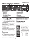
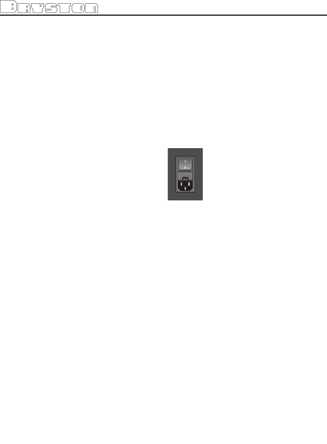
POwER INLET & SwITCH
Located on the right hand side of the
rear panel, adjacent to the IEC power
cord socket is a large computer-style
switch that controls the main electrical
power to the unit. This is the ONLY
switch that actually completely turns
off all power to the unit. When the SP2
is connected to an appropriate AC
power source, and the power switch is switched to
the ‘I’ position, the unit automatically sets itself
into a STANDBY power mode, where-in only the
minimum necessary circuitry to respond to the
remote control’s power-on command or the
momentary push-button power switch on the front
panel are active. The RED standby LED on the
front panel illuminates.
Pressing the momentary POWER bush-button
switch on the front panel or the POWER button on
the remote immediately takes the unit out of its
STANDBY mode into its normal operating mode.
This is indicated by the illumination of the front
panel LCD display, the illumination of the LED cor-
responding to the source you last selected, and the
units LED operating mode indicators.
NOTE:
If your unit’s LCD backlight does not illuminate
when the SP2 is plugged into an operating out-
let, and switched out of STANDBY mode, please
check to see that the rear panel main power switch
{mains switch} is in the ON position.
If the SP2 is to be unused for an extended
period of time (i.e. a vacation) it is strongly recom-
mended that it be turned off using the main power
switch on the back panel.
3


