


33
Tab 6, 14
English Tab 2, 10 Tab 3, 11 Tab 4, 12 Tab 5, 13
Tab 8, 16Tab 7, 15
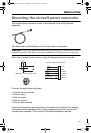
INSTALLATION
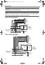
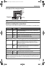
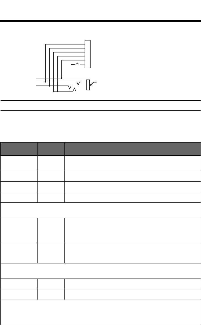
Helicopter (U174) connection diagram
Note: Barrel ground (gnd) refers to aircraft grounds.
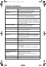
Details on making the connections
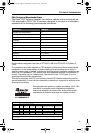
The pinouts for the optional installed connector are detailed in the table below:
Pin number Color Purpose
1 Red V+IN: Headset power (10-32 VDC). Use a
1
/4 amp fuse or
a
1
/2 amp circuit breaker.
2 Black GND: System ground. Connect to the existing audio ground.
3 White COMM L: Phone communication: Left.
4BlueCOMM R: Phone communication: Right.
Note: For stereo operation, connect the left and right channels to their respective positions. For
monaural operation, connect pins 3 and 4 together, and to the tip of the existing phone jack.
5 White MIC HI: Microphone/Hi-audio. Connect to the portion of the
existing microphone jack that corresponds to the ring
position of a headset microphone plug. Do not connect to
the tip (PTT) segment.
6White/
Blue
MIC LO: Microphone/Lo-ground. Connect to the portion of
the microphone jack that corresponds to the barrel position
of a headset microphone plug.
Note: If the microphone works on radio transmit but not through the intercom, check pin 6. It
may be incorrectly wired to the PTT segment of the microphone jack.
Comm Shield Black Shield from Comm L and Comm R wire pair.
Mic Shield Black Shield from Mic Hi and Mic Lo wire pair.
Note: The wires connecting pins 3 and 4 and pins 5 and 6 are shielded, twisted pairs with a
black wire shield termination exiting each pair. If the existing wiring is not shielded, connect the
shields to the existing audio wiring shields, or connect the shield from Comm L and Comm R
wire pair to audio ground.
Barrel
(audio gnd)
Existing single 4-
prong jack
Existing wiring to
helicopter intercom/
audio panel
10-32
V DC
6 MIC LO
5 MIC HI
4 COMM R
3 COMM L
2 GND
1 V+IN
1/2A
WHT/BLU
WHT
BLU
WHT
BLK
RED
00_Cavu.book Page 33 Wednesday, April 25, 2012 10:10 AM