


32
Tab 3, 11
Tab 8, 16 Tab 7, 15 Tab 6, 14 Tab 5, 13 Tab 4, 12
EnglishTab2, 10
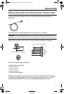
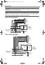
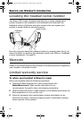
INSTALLATION
CAUTION: Do not use excessive force or bend the installed connector. This may
damage or break internal solder joints.
Note: The aircraft panel connector cannot be installed in an audio system using
transformer-coupled audio outputs. Contact the Bose
®
Technical Support, using
the contact information on page 37 of this guide for details.
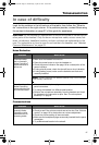
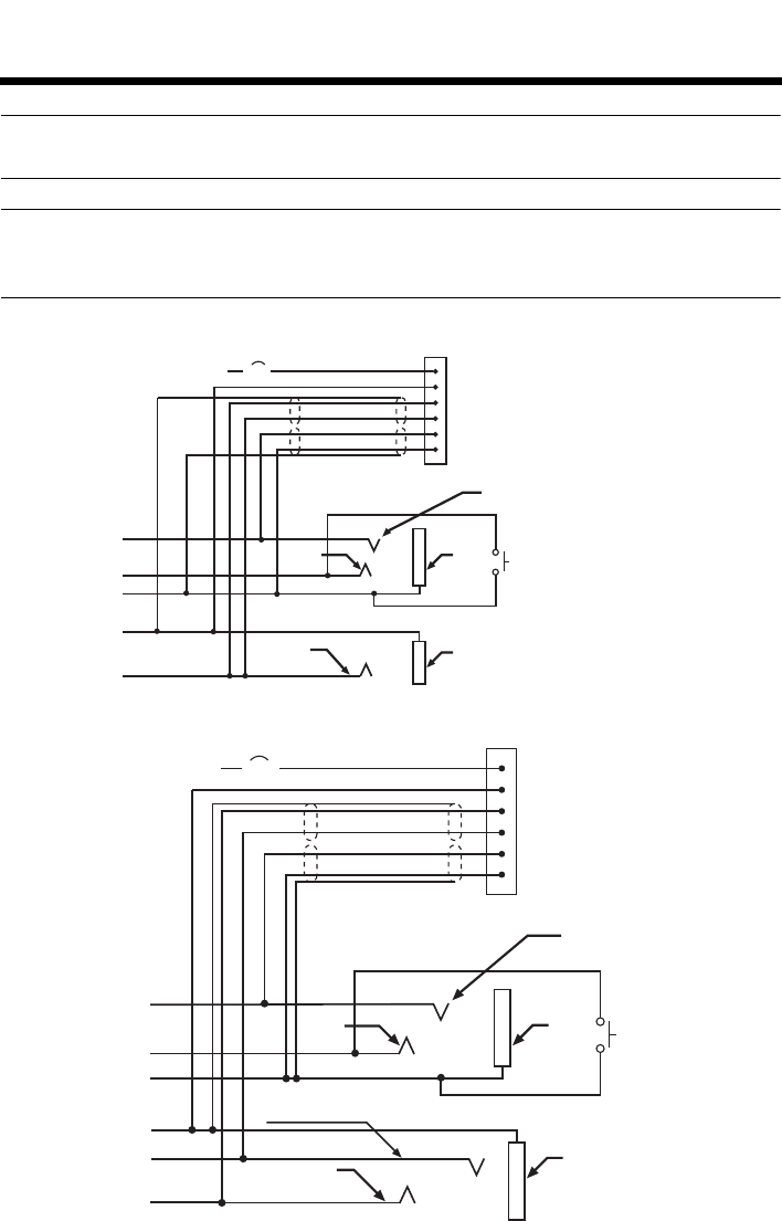
Mono connection diagram
Stereo connection diagram
10-32
V DC
1/2A
1V+IN
2 GND
3 COMM L
4 COMM R
5 MIC HI
6 MIC LO
RED
BLK
WHT
BLU
WHT
WHT/BLU
BLK/WH
BLK/WH
Ring
(audio)
Existing PTT
switch
and wiring
(no connection to
Bose headset)
Microphone - Jack
TPP
(PTT)
Barrel
(gnd)
Headphone - Jack
Barrel
(audio gnd)
Tip
(phone audio)
Existing wiring to
aircraft intercom/
audio panel
Existing wiring to
aircraft stereo
intercom/audio panel
10-32
V DC
1/2A
1V+IN
2 GND
3 COMM L
4 COMM R
5 MIC HI
6 MIC LO
RED
BLK
WHT
BLU
WHT
WHT/BLU
BLK/WH
BLK/WH
Audio
Existing
PTT switch
and wiring
(no connection to
Bose headset)
Microphone - Jack
TPP
(PTT)
Barrel
(gnd)
Stereo Headphone - Jack
Barrel
(audio gnd)
Tip
(phone audio left)
Phone
audio (right)
00_Cavu.book Page 32 Wednesday, April 25, 2012 10:10 AM