


Page 9
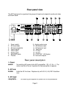
4. Video
outputs
-
Outputs labeled MON1, MON2, V1, and V2. Provides composite
video output to a TV, monitor, or VCR for viewing or recording the
video signal.
5. Video
inputs
-
Inputs labeled TV-V3, V2, V1, and DVD/VLD used to connect the
A/V source to provide the video signal that the preamplifier can
switch between.
6. Digital
inputs
-
Inputs labeled V1, V2, TV-V3, TUNER, DVD/VLD, and CD used to
connect a digital audio signal from your source to the AVP
preamplifier. The incoming signal may be either a PCM or Dolby
Digital signal, you configure the input (in the setup menu) according
to your system needs. These inputs are coaxial only.
PLEASE NOTE:
The DIGITAL inputs on the AVP1030 will only accept an Industry Standard Consumer
Audio
DIGITAL
input signal. (See setup procedure in this manual)
When you connect an Dolby Digital source to an AVP with Dolby Digital, the
signal
must
be an Industry Standard Consumer Audio
DIGITAL
signal into the
AVP1030.
Laserdisc players normally have an Industry Standard Consumer Audio RF
Dolby Digital signal. This type of Dolby Digital signal requires a Dolby Digital RF
demodulator to be placed between the player and the AVP1030 This converts
the RF Dolby Digital signal, out of the laserdisc, to a Dolby Digital DIGITAL
signal. This signal can then be processed by the AVP1030 digital inputs.
7. SEND/RCV
inputs
-
Not currently used. For future applications.
8. PRE-OUTS
-
Provides variable level audio output for sending to a power
amplifier or other audio component. They carry the same signal as
the FRONT L and FRONT R outputs.
9. Analog audio
inputs
-
Line level inputs for connecting your audio components to the
system (DVD/VLD, CD, and TV-V3).
10. AM antenna
input
-
Connection for the AM antenna. 75 Ohms.