


Page 8
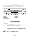
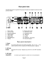
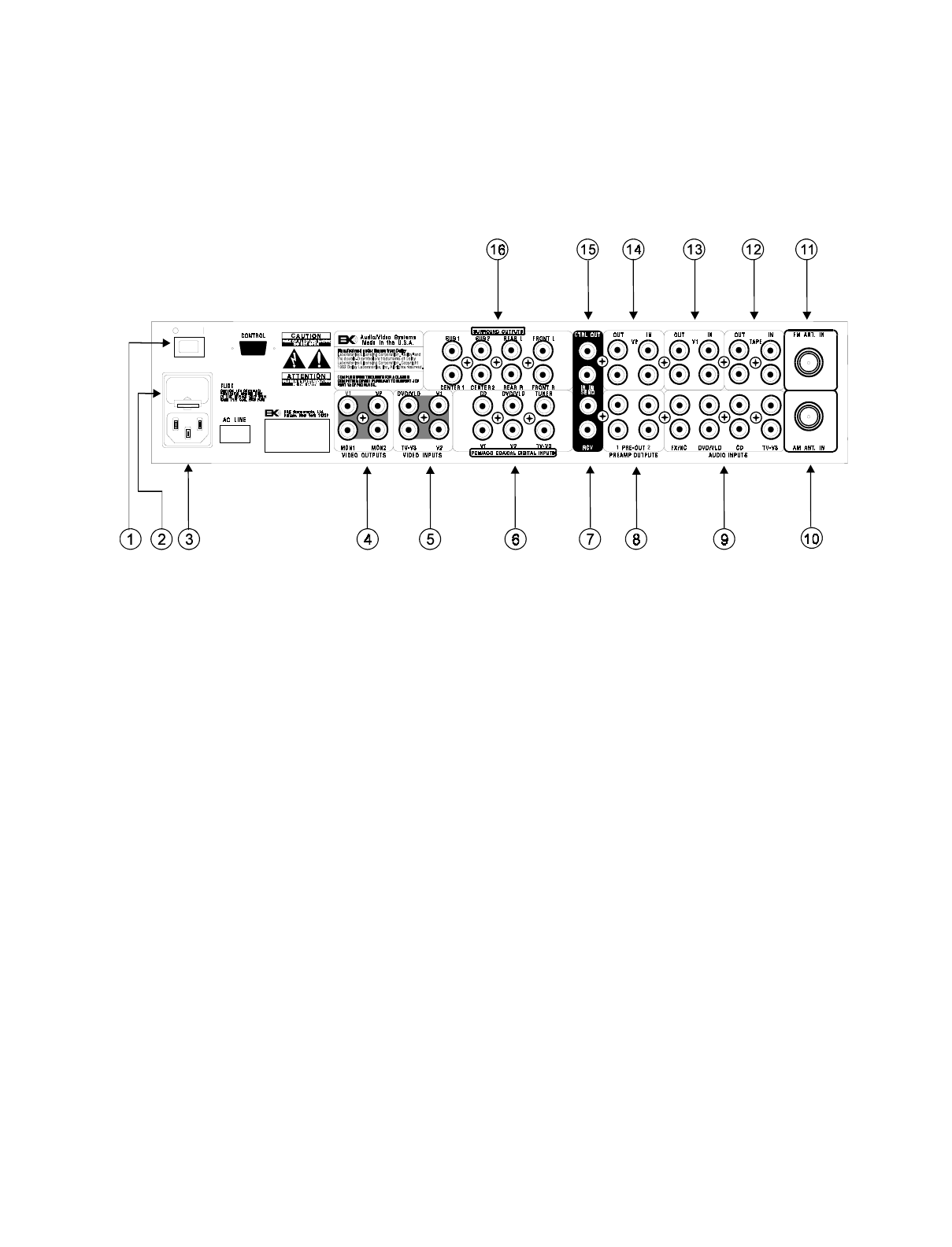
Rear panel view
The AVP back panel is organized into groups of inputs and outputs for audio and video
as shown below.
1. Power switch
9. Analog audio inputs
2. AC fuse holder
10. AM antenna input
3. AC input receptacle
11. FM antenna input
4. Video outputs
12. Tape loop
5. Video inputs
13. V1 loop
6. Digital inputs
14. V2 loop
7. Send/RCV jacks
15. CTRL OUT / IR IN jacks
8. Preouts
16. Surround outputs
Rear panel description
1. Power
switch
-
For switching AC power to the AVP preamplifier. Off = O, On = I. The
rocker must be in the on (I) position for the preamplifier to operate.
2. AC fuse
holder
-
Holds the AC Line fuse. Replace only with 0.5 A (½ A) 250 V fast blow
fuse.
3. AC input
receptacle
-
For attaching the supplied AC power cord to the preamplifier.