


7
ULTRACURVE PRO DEQ2496
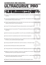
2. CONTROL ELEMENTS
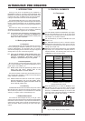
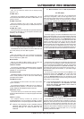
The PAGE key allows you to select the various pages
within one menu.
The functions performed by the keys A and B depend on
the selected menu and are indicated in the display.
This is the LC display of your ULTRACURVE PRO.
The DEQ2496 has three DATA WHEELS, which can be
used to select and edit various parametersagain
depending on the currently selected menu. Often, they
perform a dual function, i.e. you can edit by turning and
pressing a data wheel. Pressing the data wheels also
changes the scaling of many parameters (step width) or
confirms/resets previously made entries.
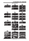
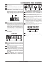
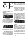
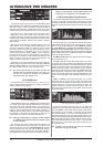
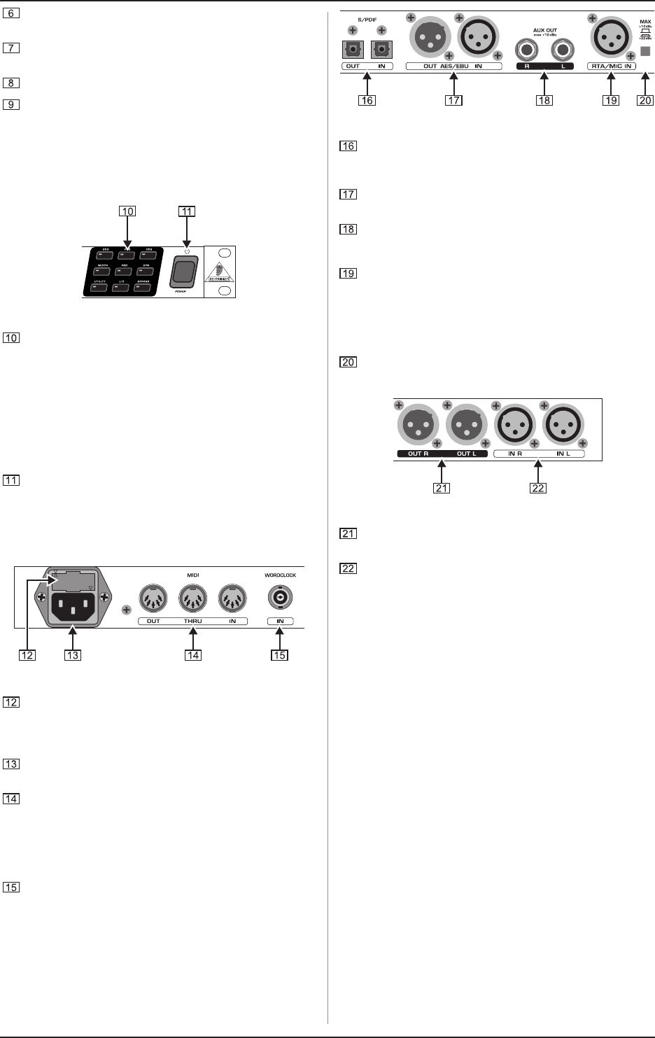
Fig. 2.3: The menu keys of the DEQ2496
With the menu keys you can select the individual menus
of the various modules. They can also be used to select
specific pages from these menus (like PAGE key). Each
of these keys has a built-in LED, which lights up when the
corresponding module starts modifying the sound. When
the DEQ2496 receives MIDI data, the LED of the UTILITY
key lights up briefly. Keep this key pressed for about 1 s
to bypass active modules or re-activate disabled ones.
This function refers only to those modules which can be
edited in the BYPASS menu (see chapter 3.7).
Use the POWER switch to put the DEQ2496 into operation.
This switch should be set to Off before you connect the
unit to the mains.
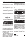
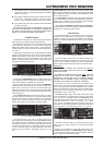
2.2 Rear panel
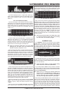
Fig. 2.4: Mains, MIDI and wordclock connectors
The FUSE HOLDER holds the mains fuse of the DEQ2496.
Blown fuses must be replaced by fuses of the same type
and rating. Please see the SPECIFICATIONS for further
details.
The mains connection is made using the enclosed power
cord and a standard IEC receptacle.
The MIDI jacks enable the DEQ2496 to communicate with
a computer or other MIDI equipment. Incoming MIDI data
are received on the MIDI IN, outgoing MIDI data are sent
via the MIDI OUT. Received MIDI data are also present at
the MIDI THRU jack, so as to pass them on unmodified to
other devices.
Use the WORDCLOCK input to synchronize your
DEQ2496 to external equipment via a wordclock signal.
This connector is on a BNC coaxial jack.
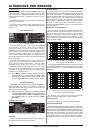
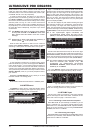
Fig. 2.5: Digital interfaces and RTA microphone input
Your DEQ2496 features a digital optical interface for the
transmission/reception of data in both AES/EBU and
S/PDIF formats.
The digital AES/EBU interface (XLR connectors) also
sends/receives AES/EBU or S/PDIF signals.
The AUX OUT phone jack is an additional stereo output,
which allows you to tap the audio signal present at the
digital outputs in analog form.
The RTA/MIC IN XLR connector can be used to connect
a measurement microphone providing an input signal for
the real-time analyzer or SPL meter. This connector has a
switchable +15 V phantom power supply for condenser
microphones and can be set to microphone or line
sensitivity (see chapter 3.11).
The MAX switch raises the maximum level present at the
MAIN inputs/outputs from +12 dBu to +22 dBu.
Fig. 2.6: Input and output connectors
These balanced XLR connectors provide the analog output
signal of the DEQ2496.
These balanced XLR inputs are used to connect analog
input signals.