


12
ULTRACURVE PRO DEQ2496
3. MENU STRUCTURE AND EDITING
Compressor only:
The compressor features an additional KNEE function, which
makes it possible to achieve a very unobtrusive and musical
form of compression. The KNEE parameter controls the area
around the threshold point, in which the compressor curve is
rounded out.
The KNEE setting range is from 0 to 30 dB and can be entered
with the large data wheel.
A long key press on the B key resets the parameters on the
dynamics pages, however, not the LIMITER settings (see next
chapter 3.4.1).
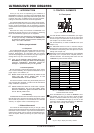
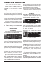
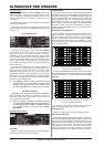
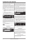
3.4.1 LIMITER menu
Fig. 3.15: LIMITER menu
On page 2 of the DYN menu, you can change to the LIMITER
page with key B. In general, a limiter can be considered a
compressor, however, one which always uses a maximum
attenuation factor, thus effectively suppressing all signal peaks
and protecting connected power amps and speakers from
overload and possible damage. Here, too, the display shows
how the signal is limited. Also available are a LEVEL meter (in
this case displaying the output signal) and a GAIN meter showing
the level reduction.
The HOLD function determines how long the signal level is
reduced, once the threshold has been exceeded (upper data
wheel). Only when this time has expired (0 - 1,000 ms), will the
RELEASE parameter take over. The control range of the
THRESHOLD parameter (large data wheel) is from 0 to -24 dB,
RELEASE can be adjusted between 20 and 4,000 ms (lower
data wheel). A long key press on the B key resets the LIMITER
parameters to their default values.
+ The LIMITER function is always active and cannot
be switched off. It is also active in bypass mode,
however, only works to a limit value of 0 dB, so as
to avoid digital distortion occurring on the outputs.
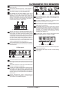
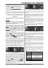
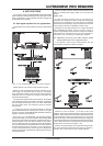
3.5 UTILITY menu
The UTILITY menu provides basic defaults settings (GENERAL
SETUP) and MIDI configurations on two pages. The upper and
lower data wheels select the parameters, which can then be
edited with the large data wheel.
+ When you keep the UTILITY key pressed for about
1 s, the ULTRACURVE PRO will be locked and cannot
be accessed any longer (PANEL LOCKED). Keep the
key pressed again to unlock the unit (PANEL
UNLOCKED).
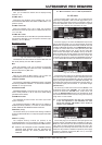
GENERAL SETUP (page 1)
Fig. 3.16: UTILITY menu (page 1)
CONTRAST
Here you can adjust the display contrast to adapt it optimally to
studio/stage environments (large data wheel).
CHANNEL MODE
As already mentioned, you can choose between DUAL MONO
and STEREO LINK mode. In DUAL MONO mode all settings for the
left and right stereo sides can be entered separately. When you
switch to STEREO LINK mode, the settings of one stereo side
will be copied to the other. You can select whether the left side
shall be copied to the right, or the right side to the left (COPY
LEFT -> BOTH or COPY RIGHT -> BOTH). All subsequent editing
will have an effect on both sides simultaneously. Finally, to
activate one CHANNEL MODE, confirm your entry with the B key
(ACCEPT MODE).
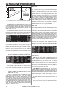
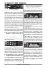
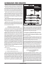
GEQ MODE (TRUE RESPONSE)
Due to the design of conventional equalizers there is always a
difference between the adjusted frequency response curve
and the resulting real frequency response. This difference
depends on the frequency and the amount of boost/cut applied.
Adjacent frequency ranges have a mutual influence on each
other, so that the amounts of boost/cut in the individual frequency
bands are added together.
Fig. 3.17: Graphic equalizer without frequency response
correction (UNCORRECTED)
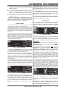
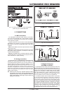
The setting UNCORRECTED retains this mutual influence. With
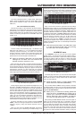
a specially developed algorithm the ULTRACURVE PRO can make
up for this phenomenon. To use this characteristic, select TRUE
RESPONSE.
Fig. 3.18: Graphic equalizer with frequency response
correction (TRUE RESPONSE)
The resulting real frequency response now corresponds
exactly to the setting made with the graphic equalizer.
GAIN OFFSET (EQ)
Here, you can correct the overall gain of the EQ modules.
RTA NOISE CORRECTION
The algorithm used by the RTA (Real-Time Analyzer, warped FFT)
leads to inaccuracies with wide-spectrum signals such as noise,
due to the asymmetric overlapping of individual frequency ranges.
When the built-in noise generator is on or the AVRG setting in the
RTA menu has been selected, this correction will be made
automatically, and needs not be switched on manually. With all
other signals, however, this function should be off; otherwise,
the individual frequency bands might be displayed incorrectly.