


13
ULTRACURVE PRO DEQ2496
3. MENU STRUCTURE AND EDITING
SHOW MESSAGE BOX
Here, you can determine whether the unit displays dialog
windows or not.
RTA/MIC INPUT
Controls the input sensitivity of the RTA/MIC input. You can
choose between LINE LEVEL, MIC LEVEL and MIC LEVEL +15 V
(phantom power).
RTA/MIC LINE LEVEL
When the RTA/MIC input is set to LINE, this parameter
determines the maximum input level (for 0 dBFS (full-scale) from
-14 to +22 dBu).
RTA/MIC MIC LEVEL
When the RTA/MIC input is set to MIC, this parameter determines
the sensitivity depending on the microphone connected (input
sensitivity: -42 to -6 dBV/Pa).
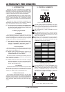
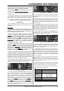
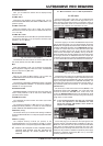
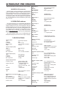
MIDI SETUP (page 2)
Fig. 3.19: UTILITY menu (page 2)
The DEQ2496 can both transmit and receive MIDI data and
thus works perfectly with other MIDI equipment.
MIDI
When this parameter is ON, you can display all subsequent
MIDI configuration categories. When set to OFF, the DEQ2496
does not respond to any MIDI data.
MIDI CHANNEL
Here you can select the MIDI channel (1-16) on which the
ULTRACURVE PRO transmits and receives MIDI data.
CONTROL CHANGE
The exchange of CONTROL CHANGE data refers to the GEQ
module only (CONTROL CHANGE 1 - 31: left channel / CONTROL
CHANGE 33 - 63: right channel).
PROGRAM CHANGE
PROGRAM CHANGE commands (both send and receive) are
used to recall presets #1 to 64 as well as the default setting
(preset #0: INITIAL DATA).
SYSTEM EXCLUSIVE
Your DEQ2496 can both transmit and receive sys-ex data
(system exclusive).
The transmission/reception of MIDI data can be enabled or
disabled specifically (ON/OFF). To be able to receive software
updates, RECEIVE SYSTEM EXCLUSIVE must be ON.
DUMP EDIT (A key)
This function allows you to transfer active settings via MIDI to
another ULTRACURVE PRO or a computer equipped with a MIDI
interface.
DUMP ALL (B key)
The complete memory contents (all presets) of the
ULTRACURVE PRO can be transferred via MIDI to another
ULTRACURVE PRO or a computer equipped with a MIDI interface.
+ Caution: the reception of the complete memory
contents from another unit will overwrite all
existing settings! All saved presets will be
retained.
+ More information on MIDI can be found in chapter
5.1 MIDI connections and 7.1 MIDI implementation.
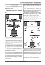
3.6 I/O menu
On the first three pages of this menu you can determine the
input/output configuration, while the fourth page allows you to
adjust the output signal delay function, for example to make up
for run-time differences, which occur when several P.A. speaker
stacks set up at a distance from each other are used.
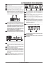
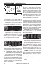
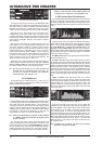
Fig. 3.20: I/O menu (page 1)
On the first page you can select the DEQ2496s input source
with the large data wheel. You can choose between the analog
MAIN INPUT, the digital inputs (DIGITAL XLR or DIGITAL OPT) and
the built-in PINK NOISE generator. Use the NOISE GAIN parameter
to adjust the volume level of the noise generator (lower data
wheel). The setting range is from -60 to 0 dB. The upper data
wheel controls the sample rate (CLOCK) used by the device.
When the digital input has been selected, the sample rate cannot
be changed, because the DEQ2496 tracks the sample rate
contained in the input signal. When the PINK NOISE generator is
on, the modules DEQ and DYN (not LIMITER) are switched off.
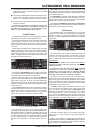
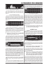
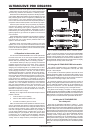
Fig. 3.21: I/O menu (page 2)
On the second menu page you can determine the signal source
for the AUX output and the digital outputs. Selectable options are
the unprocessed input signal (MAIN IN or DIG. IN), the processed
signal, post-graphic/parametric EQ (BEHIND GEQ/PEQ), the
processed signal post-EQ and post-dynamics module (DYN), or
the processed signal post-all modules, i.e. post-stereo imager
(BEHIND WIDTH).
Use the A key to select the consumer format (S/PDIF) or the
professional digital format (AES/EBU). The upper data wheel
controls the resolution, DITHER (OFF, 24-bit, 20-bit and
16-bit). The NOISE SHAPER function to be activated with the B
key reduces the dither-induced noise by moving it to a frequency
range where it is less audible.
+ If the connected sample rate does not correspond
to the rate adjusted on the DEQ2496, this field
shows the message UNLOCKED, which mutes all
outputs of the DEQ2496.
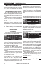
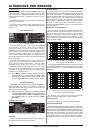
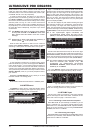
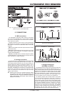
Fig. 3.22: I/O menu (page 3)
On the third page you can determine the input signal for the
real-time analyzer. Selectable options are MAIN IN (or DIG. IN),
MAIN OUT, AUX OUT/DIG. OUT (XLR and optical) and RTA/MIC
input. When you select the RTA microphone input, the A key
switches the input sensitivity from MIC to LINE, and vice versa,
while the B key enables or disables the phantom power supply
required for condenser microphones (MIC +15 V), if the input
sensitivity has been set to MIC.