


14
ULTRACURVE PRO DEQ2496
3. MENU STRUCTURE AND EDITING
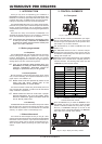
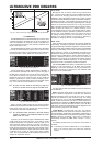
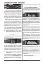
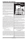
Fig. 3.23: I/O menu (page 4)
On the fourth page of the I/O menu, the ULTRACURVE PRO
DEQ2496 allows you to delay either the MAIN output signal or the
AUX signal, which is useful, for example, when the connected
speakers are positioned at a distance from each other, which
results in audible run-time differences and/or phase cancellation.
With the A key you can select the left or right stereo side.
Independently of the Stereo LINK mode both sides can be
processed separately. Keep the key pressed to edit both sides
simultaneously. The B key determined whether the MAIN or AUX
output signal is processed. Keep this key pressed to reset all
delay settings.
With the upper data wheel you can determine the unit for the
delay settings. You can choose between milliseconds (0 - 300
ms), feet (0 - 338.08 ft) or meters (0 - 103.08 m). If feet or meters
have been selected, the lower data wheel adjusts the current
ambient temperature in °Fahrenheit or °C, so as to ensure an
optimum delay response pattern (TEMP.). This is necessary
because the speed of sound largely depends on the ambient
temperature. For example, at 20 °C ambient temperature, the
speed of sound is 343.6 m/s. The higher the temperature, the
higher the speed of sound (plus 0.6 m/s per °C).
Depending on the channel selected, the large data wheel now
controls the left or right stereo side of the output signal (DELAY
LEFT and DELAY RIGHT) or even both at the same time. Press
the wheel to select a coarse or fine adjustment scale.
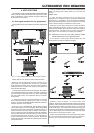
+ The AUX output allows you to send out both the
delayed and the undelayed signal. This way, you
can set up a delay line without any additional
equipment (see also chapter 4.4).
3.7 BYPASS menu
The BYPASS menu includes one page, on which you can
select various BYPASS parameters for making comparisons
between different sound settings.
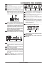
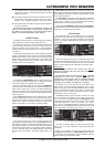
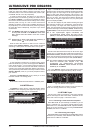
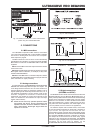
Fig. 3.24: BYPASS menu
In DUAL MONO mode you can activate the relay bypass function
for the left (upper data wheel: BYPASS LEFT) or right stereo
side (lower data wheel: BYPASS RIGHT). This connects the
analog left or right input of the unit to the corresponding analog
output, so that the signals bypass the modules completely. In
STEREO LINK mode the upper and lower data wheels disable
the modules of both sides simultaneously, so that only the
unprocessed input signal can be heard (BYPASS ALL).
+ Keeping the BYPASS key pressed in DUAL MONO
or STEREO LINK mode activates the bypass relays
of both channels.
Turn the large data wheel to select individual modules, and
press it to remove them from the signal path. The same can be
achieved by pressing the B key (BYPASS MODULE). Keeping
this key pressed for a while will reset all BYPASS settings.
Keeping the module keys pressed for a while (GEQ, PEQ etc.)
will enable/disable the bypass function for individual modules.
+ Please note that the WIDTH function (stereo
imager) is not available in DUAL MONO mode, and
is therefore not displayed in the BYPASS menu.
3.8 RTA menu (Real-Time Analyzer)
Your ULTRACURVE PRO DEQ2496 features an FFT real-time
analyzer for the graphic representation of all frequency ranges
(61 bands). Additionally, this menu includes an AUTO EQ function
(AEQ) for automatic frequency response correction (see chapter
3.8.1).
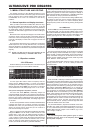
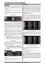
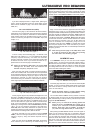
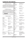
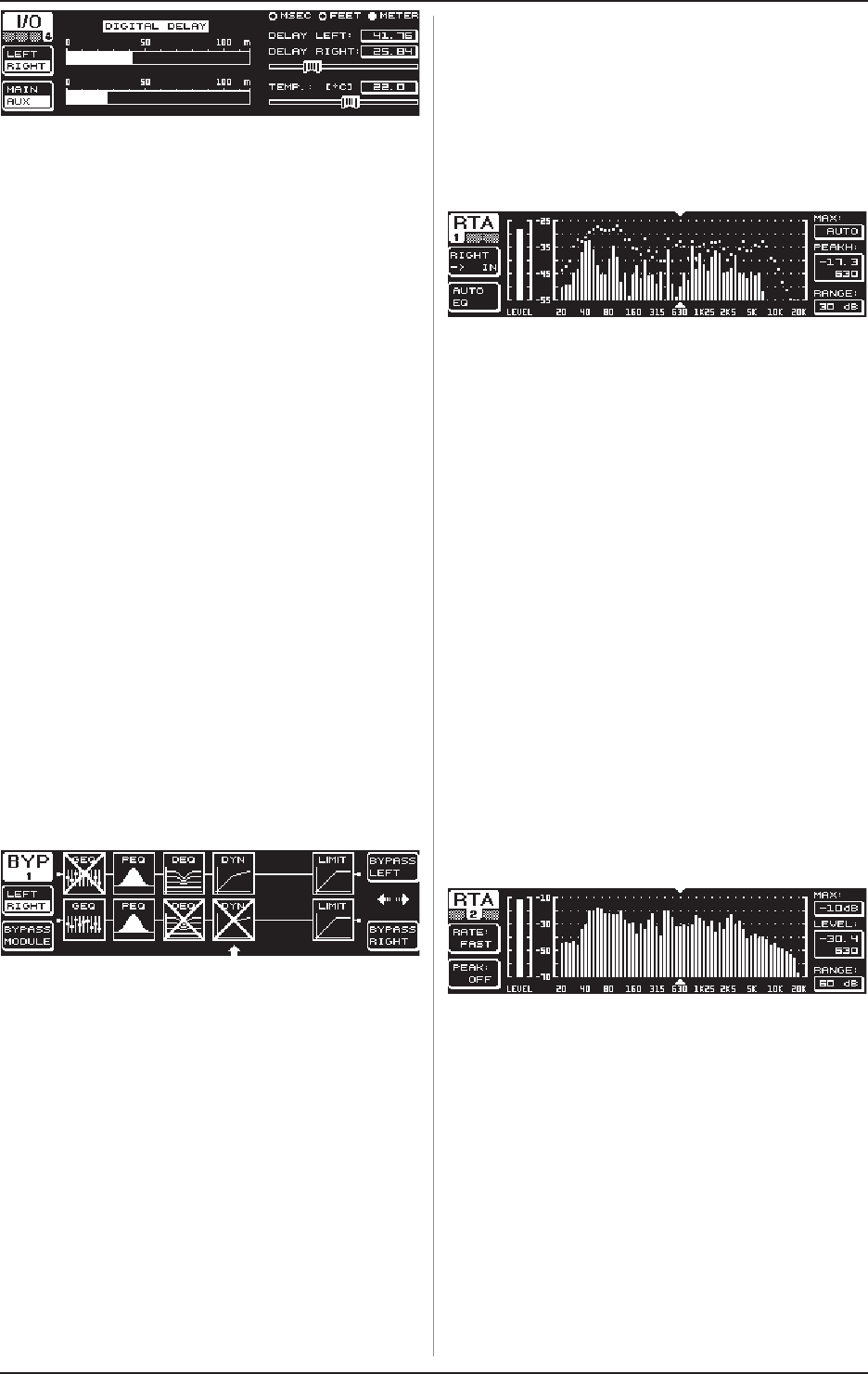
Fig. 3.25: RTA menu (page 1)
On the first page, the A key selects the analyzer input signal.
These settings are the same you can adjust on page 3 of the I/O
menu. You can choose between the options MAIN IN or DIG IN
(L + R IN), MAIN OUT (L + R OUT), AUX. OUT/DIG. OUT (L + R
DIGOUT) and RTA IN (MIC/LINE). Use the A key for selection.
Keep the key pressed to determine which input signal is displayed
by the analyzer (left, right or complete input signalnot available
if RTA IN has been selected).
RTA MIC/LINE IN displays the signal present at the RTA/MIC
input (see chapter 3.11).
The MAX. parameter (upper data wheel) allows you to select
an excerpt of the entire level spectrum, depending on the actual
magnitude of the signal level. The adjusted dB value (0 to -60 dB)
refers to the upper limit that will be displayed. Press the wheel to
activate the AUTO function. Now the MAX value is adjusted
automatically, depending on the signal level. RANGE (lower data
wheel) determines the dynamic range displayed in four steps
(15, 30, 60 or 90 dB). Depending on the selected MAX value, the
dynamic range displayed will be extended towards the bottom
end.
LEVEL or PEAKH (large data wheel) allow you to select
specifically each of the 61 frequency bands and display their
current volume levels (LEVEL) or PEAK values referenced to the
adjusted frequency. The cursor arrows above and below the
graphic indicate the currently selected frequency range. The
level of the main signal is shown by the LEVEL meter to the left
of the RTA display.
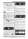
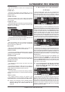
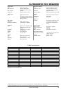
Fig. 3.26: RTA menu (page 2)
On the second page of the RTA menu you can adjust the
release time in four steps (FAST, MID, SLOW and AVRG) with
the A key (RATE). If set to FAST, MID or SLOW, the RTA uses
peak detectors. If set to AVRG, it calculates average values
from the signal levels. In this mode, the analyzer seems to be
processing slower than usual. The B key (PEAK) selects in five
steps how fast the displayed signal peaks disappear again (FAST,
MID, SLOW, HOLD and OFF). If set to HOLD, the maximum values
of the individual frequency bands are frozen. If you press the
B key for about 1 s, the frozen level peaks are reset and can
be calculated anew.
+ If PEAK is set to HOLD, the name of the LEVEL
parameter changes to PEAKH.