


iv
Emerge EMS Installer/User Guide
v
L I S T O F F IG U R E S
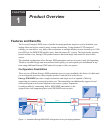
Figure 1.1: A standard Emerge EMS1000P conguration driving two display/speakers sets..........1
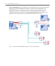
Figure 1.2: A typical Emerge EMS1000MP conguration driving up to eight displays...................2
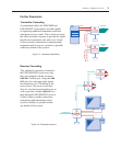
Figure 1.3: Cascaded transmitters ...................................................................................................3
Figure 1.4: Cascaded receivers ........................................................................................................3
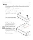
Figure 2.1: Applying the self adhesive rubber feet ...........................................................................6
Figure 2.2: The rear mounting slot ...................................................................................................6
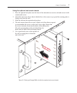
Figure 2.3: Placing an Emerge EMS unit within the optional rack mount chassis ..........................7
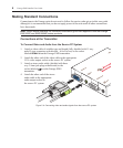
Figure 2.4: Connecting video and audio signals from the source PC system...................................8
Figure 2.5: Connecting a monitor and speakers to the transmitter unit...........................................9
Figure 2.6: Overall maximum link length (1000 feet) when one receiver is connected..................10
Figure 2.7: Connecting the link cable to the EMS1000P transmitter unit......................................10
Figure 2.8: Connecting up to four link cables to the EMS1000MP-T transmitter unit ..................11
Figure 2.9: Connecting the power adaptor to the transmitter unit.................................................12
Figure 2.10: Connecting the power adaptor to the power cord......................................................12
Figure 2.11: Connecting displays and speakers to the receiver unit ..............................................13
Figure 2.12: Overall maximum link length (1000 feet) when one receiver is connected................14
Figure 2.13: Connecting the link cable to the receiver unit............................................................14
Figure 2.14: Connecting the power adaptor to the receiver unit....................................................15
Figure 2.15: Connecting the power adaptor to the power cord......................................................15
Figure 2.16: Valid multiple cascade connections and their effects on overall link lengths ............17
Figure 2.17: Connecting multiple transmitters in a cascade arrangement.....................................18
Figure 2.18: Connecting the audio/visual outputs of one transmitter to the inputs of the next......19
Figure 2.19: Connecting multiple receivers in a cascade arrangement .........................................20
Figure 2.20: Connecting the link output of one receiver to the link input of the next.....................21
Figure 3.1: Location of the red and green operation indicators ...................................................23
Figure 3.2: Location of the brightness and sharpness adjustment dials.........................................24
Figure 3.3: Using a high contrast image to assist with sharpness adjustments .............................24
Figure 3.4: Location of the skew compensation adjustment dials ..................................................25
Figure 3.5: Creating a suitable skew test pattern within a paint package......................................25
Figure 3.6: The supplied skew test pattern showing green slightly retarded
relative to the red and blue..............................................................................................................26
Figure 3.7: A skew compensation dial showing its middle neutral position
and its two maximum positions .......................................................................................................26
Figure 3.8: The two skew compensation dials showing how they affect each of the colors............27