


25
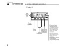
4 - Operations
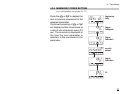
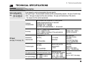
effectiveness of the PID algorithm.
Setting 1, the overshoot control is
disabled.
Control output
high limit
It specifies the maximum value the
control output can be set
Control output
hysteresis
Control output hysteresis span, set
in % of the full scale.
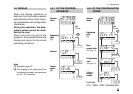
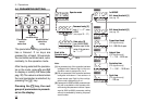
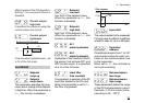
2nd GROUP
Setpoint
ramp up
Setpoint
ramp down
This parameter specifies the max-
imum rate of change of the Setpoint
in digit/min. When the parameter is
Off, this function is disabled.
#sl. d
#sl. u
Off
SP
On
Hysteresis of the threshold
hy
#hy.
#Op. H
Setpoint
low limit
Low limit of the setpoint value.
When the parameter is Off, this
function is disabled.
Setpoint
high limit
High limit of the setpoint value.
When the parameter is Off, this
function is disabled.
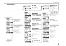
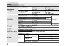
AL1
alarm hysteresis
AL2
alarm hysteresis
Hysteresis of the threshold of both
the alarms, that activate OP1 and
OP2 control output. It is specified
as a % of the full scale.
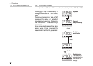
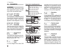
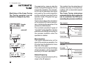
Input filter
time constant
Time constant, in seconds, of the RC
input filter applied to the PV input.
When this parameter is set to Off
the filter is bypassed.
#t.fil
#A2hy
#AIhy
#s.p. H
#s.p. l
Input shift
This value is added to the measured
PV input value. Its effect is to shift the
whole PV scale of up to ± 60 digits.
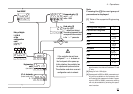
Controller
address
the address range is from 1 to 247
and must be unique for each con-
troller on the communication bus
to the supervisor.
When set to Off the controller is
not communicating
Retransmission
low range
Retransmission
high range
These parameters define the range
of the OP4 retransmission output.
Example: 4..20 mA output corre-
sponding to 20…120°C.
#rt.Hi
#rt.lo
#Addr
#In.sh
Filter response
100%
0
PV
63,2%
t.Fil
Time