


10
2 - Electrical connections
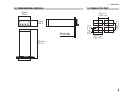
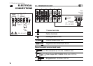
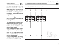
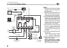
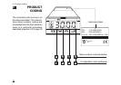
2.3 TYPICAL INSTRUMENT WIRING
B
6
V~
Supervisory
Supply V~
V~
Retransmission
4…20mA
L
N
DC voltage
Thermocouple
Current
2.5 Ω external
shunt resistor
Coil of the load
contactor
Fuse
Power
supply
switch
OP2
OP1
V
~
Fuse 0.2 A T
18V
Pt100
2 wire
transmitter
Load
Solid
state
relays
PV
54321
121110987
A
B
B
0P4
RX/TX
[6]
RS485
[5]
[4]
Notes:
1] Make sure that the power supply
voltage is the same indicated on
the instrument.
2] Switch on the power supply only
after that all the electrical con-
nections have been completed.
3] In accordance with the safety reg-
ulations, the power supply switch
shall bring the identification of the
relevant instrument. The power
supply switch shall be easily
accessible from the operator.
4] The instrument is protected with
a 0.2 A
~ T fuse. In case of fail-
ure it is suggested to return the
instrument to the manufacturer
for repair.
5] To protect the instrument internal
circuits use:
- 2 A
~ T fuses for Relay outputs
- 1 A
~ T fuses for Triac outputs
6] Relay contacts are already pro-
tected with varistors.
Only in case of 24 V ~ induc-
tive loads, use model A51-065-
30D7 varistors (on request)