


12
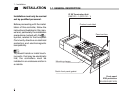
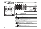
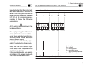
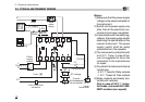
2 - Electrical connections
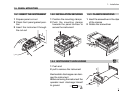
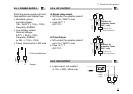
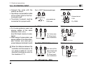
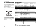
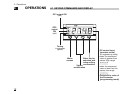
2.3.4 PV CONTROL INPUT
B
• Connect the wires with the
polarity as shown
• Use always compensation cable
of the correct type for the ther-
mocouple used
• The shield, if present, must be
connected to a proper earth.
• If a 3 wires system is used, use
always cables of the same
diameter (1mm
2
min.)
(line 20 Ω/lead maximum resis-
tance)
• When using a 2 wires system, use
always cables of the same diam-
eter (1,5mm
2
min.) and put a
jumper between terminals 5 and 6
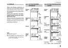
A When the distance between the
controller and the sensor is 15
mt. using a cable of 1.5 mm
2
diameter, produces an error on
the measure of 1°C.
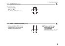
For L J K S T thermocouple type
wire resistance
150Ω max
For PT100 resistance thermometer
For 3 wires only
20 Ω/lead maxi-
mum resistance
For ∆T (2 x RTD Pt100) Special
Use wires of the
same length and
1.5 mm
2
size.
20 Ω/lead maxi-
mum resistance.
R1 + R2 must be < 320Ω
5 6 12
ABA
R1
R2
5 6 12
BBA
5 6
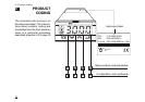
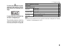
For mA, mV and V
External shunt
2.5Ω
Rj >10MΩ
With 2 wire transducer
With 3 wire transducer
external
shunt
2.5Ω
Transducer
PV
18Vdc
9 5 6
18Vdc
4…20mA
external
shunt
2.5Ω
Transducer
PV
9 5 6
mV
mA
5 6