


24
4 - Operations
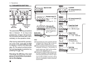
4.5 PARAMETER
1st GROUP
The controller parameters have
been organized in group, accord-
ing to their functionality area.
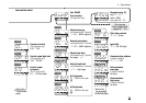
AL1 alarm
threshold
The threshold is presented only if
the controller have been configured
with 2 alarms. ( Digit L of the con-
figuration code assigned to 4 or 5)
AL2 alarm
threshold
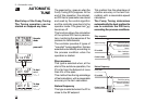
The alarm occurrences handle the
OP1 and OP2 outputs, in different
ways, according to the configured
types of alarms, as illustrated.
Proportional
band
This parameter specifies the pro-
portional band coefficient that mul-
tiplies the error (SP - PV)
Integral
time
It is the integral time value, that
#t.i.
#p.b.
#A2s.p
#AIs.p
specifies the time required by the
integral term to generate an output
equivalent to the proportional term.
When Off the integral term is not
included in the control algorithm.
Derivative
time
It is the derivative term coefficient that
specifies the time required by the pro-
portional term P to reach the level of
D. When Off the derivative term is
not included in the control algorithm.
Control output
cycle time
It’s the cycle time of the time propor-
tioning control output. The PID con-
trol output is provided through the
pulse width modulation of the digital
waveform.
Overshoot
control
This parameter specifies the span
of action of the overshoot control.
Setting lower values (0.99 —> 0.01)
the overshoot generated by a
Setpoint change is reduced. The
overshoot control doesn’t affect the
#O.C.
#t.c.
#t.d.
T
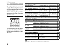
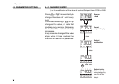
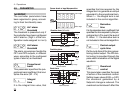
Sensor break or input disconnection
over-range
under-range
VisualisationSensor
Absolute alarm (full scale)
On
Off
Active
high
Active
low
hy
high rangelow range
Alarm threshold
On
Off
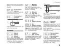
Deviation alarm
On
Off
Active
high
Active
low
hy
+ high range- low range
Alarm threshold
On
Off
SP
Band alarm
On
Off
Active
out
Active
in
hy
SP
full scalefull scale
hy
alarm threshold
On
Off