


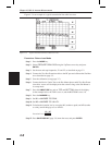

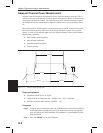

Antenna Subsystem Return Loss Test
Antenna Subsystem return loss measurement verifies the performance of the transmit and
receive antennas. This measurement can be used to analyze the performance of the antenna
before installation. The antenna can be tested for the entire frequency band, or tested to a
specific frequency range. Transmit and receive frequency measurements are conducted sep
-
arately. The following steps explain how to measure the antenna loss in return loss mode.
Required Equipment
q
Site Master Model S113C, S114C, S331C, or S332C
q
Precision Open/Short, Anritsu 22N50 or
Precision Open/Short/Load, Anritsu OSLN50LF
q
Precision Load, Anritsu SM/PL
q
Test Port Extension Cable, Anritsu 15NNF50-1.5C
q
Optional 510-90 Adapter, DC to 7.5 GHz, 50 ohm, 7/16(F)-N(M)
q
Anritsu InstaCal Module, ICN50
Device Under Test
q
Antenna Sub Assembly
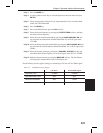
Procedure
Step 1. Press the
MODE key.
Step 2.
Select FREQ-RETURN LOSS using the Up/Down arrow key and press
ENTER.
Step 3. Connect the Test Port Extension cable to the RF port and calibrate the Site Mas-
ter as described on page 3-2.
Step 4. Press
SAVE SETUP and save the calibration set up (page 3-7).
Step 5. Connect the Device Under Test to the Site Master phase stable Test Port Exten
-
sion cable.
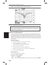
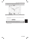
Step 6. Press the
MARKER key.
Step 7. Set markers M1 and M2 to the desired frequency.
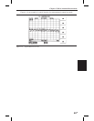
Step 8. Record the lowest return loss over the specified frequency.
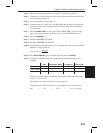
Step 9. Press
SAVE DISPLAY (page 3-8) name the trace, and press ENTER.
4-10
Chapter 4 Cable & Antenna Measurements