


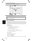
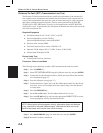
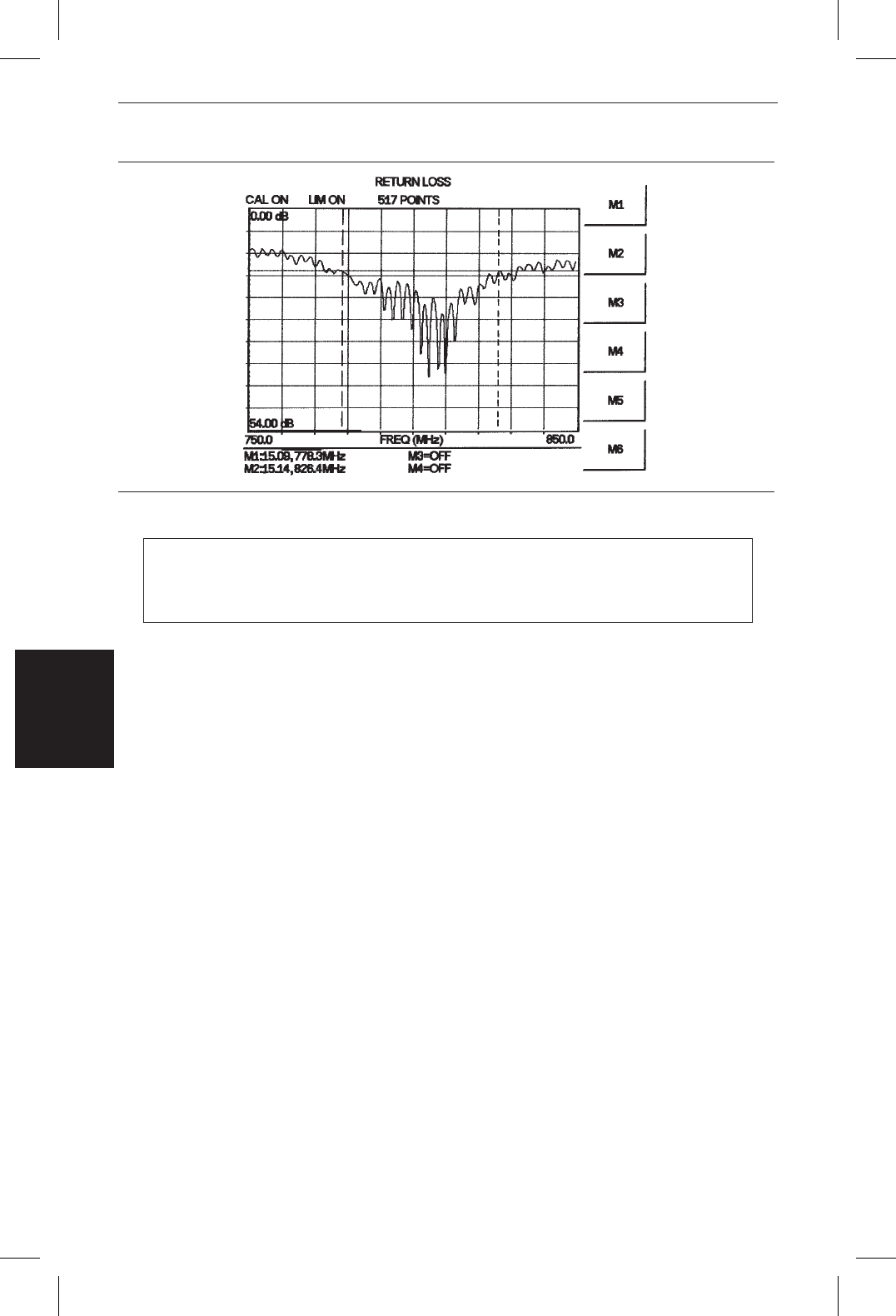
Figure 4-2 is an example of a typical system return loss trace:
NOTE: The system sweep trace should appear at an approximate return loss of
15 dB (±3 dB) on the display. In general, a 15 dB return loss is measured in the
passband of the antenna system.
Insertion Loss Measurement
The transmission feed line insertion loss test verifies the signal attenuation level of the ca-
ble system in reference to the specification. This test can be conducted with the Site Master
in either FREQ–CABLE LOSS or FREQ–RETURN LOSS mode. In Cable Loss mode, the
Site Master automatically considers the signal traveling in both directions when calculating
the insertion loss, making the measurement easier for the user in the field. Both methods are
explained below.
Required Equipment
q
Site Master Model S113C, S114C, S331C, or S332C
q
Precision Open/Short, Anritsu 22N50 or
Precision Open/Short/Load, Anritsu OSLN50LF
q
Precision Load, Anritsu SM/PL
q
Test Port Extension Cable, Anritsu 15NNF50-1.5C
q
Optional 510-90 Adapter, DC to 7.5 GHz, 50 ohm, 7/16(F)-N(M)
q
Anritsu InstaCal Module, ICN50
Device Under Test
q
Transmission Feed Line with Short
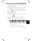
Procedure - Cable Loss Mode
Step 1. Press the
MODE key.
Step 2.
Select FREQ-CABLE LOSS using the Up/Down arrow key and press
ENTER.
4-4
Chapter 4 Cable & Antenna Measurements
Figure 4-2. Typical System Return Loss Trace