


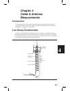
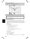


Distance-To-Fault (DTF) Transmission Line Test
The Distance-To-Fault transmission line test verifies the performance of the transmission
line assembly and its components and identifies the fault locations in the transmission line
system. This test determines the return loss value of each connector pair, cable component
and cable to identify the problem location. This test can be performed in the DTF–RE
-
TURN LOSS or DTF–SWR mode. Typically, for field applications, the DTF–RETURN
LOSS mode is used. To perform this test, disconnect the antenna and connect the load at the
end of the transmission line.
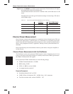
Required Equipment
q
Site Master Model S113C, S114C, S331C, or S332C
q
Precision Open/Short, Anritsu 22N50 or
Precision Open/Short/Load, Anritsu OSLN50LF
q
Precision Load, Anritsu SM/PL
q
Test Port Extension Cable, Anritsu 15NNF50-1.5C
q
Optional 510-90 Adapter, DC to 7.5 GHz, 50 ohm, 7/16(F)-N(M)
q
Anritsu InstaCal Module, ICN50
Device Under Test
q
Transmission Feed Line with Load
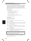
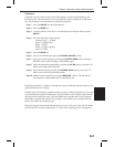
Procedure - Return Loss Mode
The following steps explain how to make a DTF measurement in return loss mode.
Step 1. Press the
MODE key.
Step 2.
Select DTF-RETURN LOSS using the Up/Down arrow key and press
ENTER.
Step 3. Connect the Test Port Extension cable to the RF port and calibrate the Site Mas-
ter as described on page 3-2.
Step 4. Save the calibration set up (page 3-7).
Step 5. Connect the Device Under Test to the Site Master phase stable Test Port Exten
-
sion cable. A trace will be displayed on the screen as long as the Site Master is
in sweep mode.
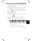
Step 6. Press the
FREQ/DIST key.
Step 7. Set the
D1 and D2 values. The Site Master default for D1 is zero.
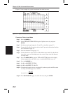
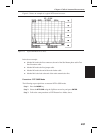
Step 8.
Press the
DTF AID soft key and select the appropriate CABLE TYPE to set the
correct propagation velocity and attenuation factor.
NOTE: Selecting the right propagation velocity, attenuation factor and distance
is very important for accurate measurements, otherwise the faults can not be
identified accurately and insertion loss will be incorrect.
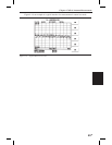
Step 9. Press
SAVE DISPLAY (page 3-8) name the trace, and press ENTER.
Step 10. Record the connector transitions.
4-8
Chapter 4 Cable & Antenna Measurements