


Step 3. Set the start and stop frequencies, F1 and F2, as described on page 3-2.
Step 4. Connect the Test Port Extension cable to the RF port and calibrate the Site Mas
-
ter as described on page 3-2.
Step 5. Save the calibration set up (page 3-7).
Step 6. Connect the Device Under Test to the Site Master phase stable Test Port Exten
-
sion cable. A trace will be displayed on the screen as long as the Site Master is
in sweep mode.
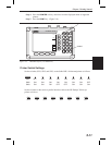
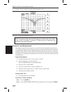
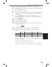
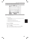
Step 7.
Press the
AMPLITUDE key and set the TOP and BOTTOM values of the dis
-
play. In the example below, the TOP is set to 2, and the BOTTOM is set to 5.
Step 8. Press the
MARKER key.
Step 9.
Set M1 to MARKER TO PEAK.
Step 10.
Set M2 to MARKER TO VALLEY.
Step 11. Calculate the measured insertion loss by averaging M1 (marker to peak) and M2
(marker to valley) as follows:
Insertion Loss
MM
=
+12
2
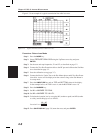
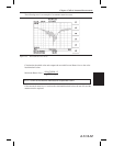
Step 12. Press
SAVE DISPLAY (page 3-8) name the trace, and press ENTER.
Step 13. Verify the measured insertion loss against the calculated insertion loss. For
example:
Type Attenuation (dB/ft)
´ Length (ft) = Loss (dB)
First Jumper
LDF4-50A 0.0325 20 0.65
Main Feeder
LDF5-50A 0.0186 150 2.79
Top Jumper
LDF4-50A 0.0325 10 0.325
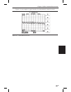
Number of connector pairs (3) times the loss per pair (in dB) equals the connec
-
tor loss: 3 ´ 0.14 = 0.42.
The insertion loss of the transmission system is equal to:
First Jumper loss + Main Feeder Loss + Top Jumper Loss + Connector Loss:
0.65 + 2.79 + 0.325 + 0.42 = 4.19 dB
4-5
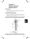
Chapter 4 Cable & Antenna Measurements