


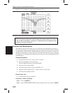
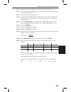
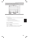
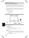
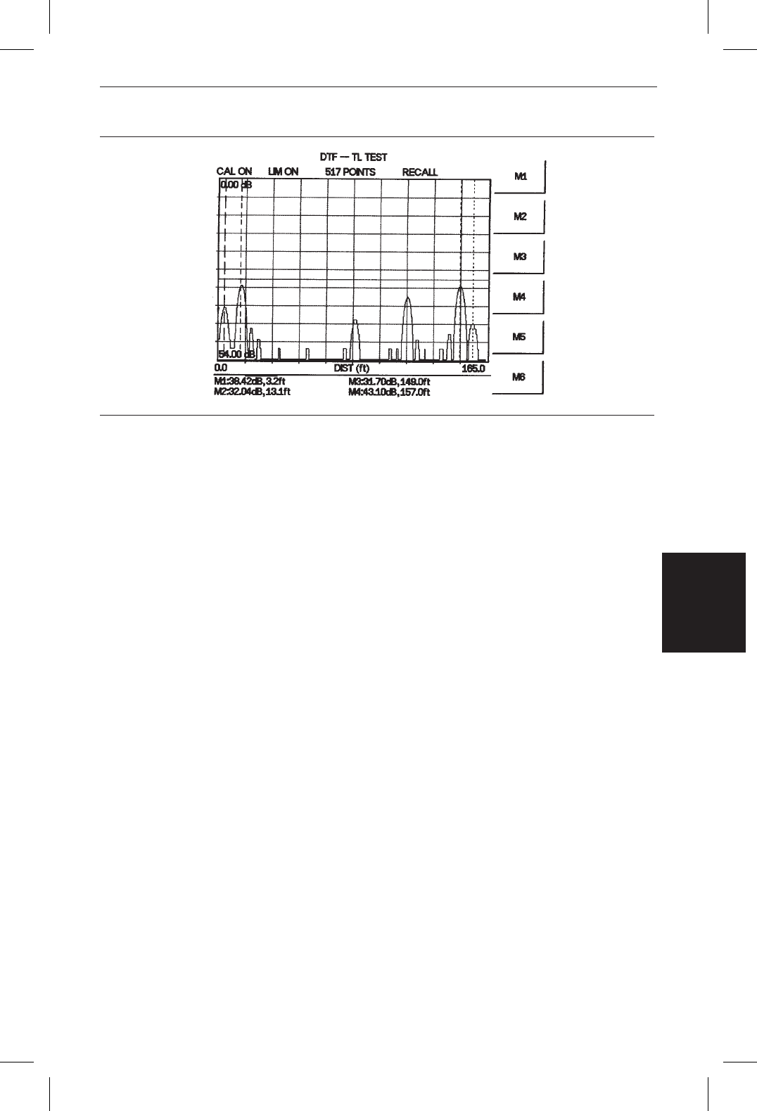
Figure 4-5 shows an example of a typical DTF return loss trace.
In the above example:
q
Marker M1 marks the first connector, the end of the Site Master phase stable Test
Port Extension cable.
q
Marker M2 marks the first jumper cable.
q
Marker M3 marks the end of the main feeder cable.
q
Marker M4 is the load at the end of the entire transmission line.
Procedure - DTF-SWR Mode
The following steps explain how to measure DTF in SWR mode.
Step 1. Press the
MODE key.
Step 2. Select the
DTF-SWR using the Up/Down arrow key and press ENTER.
Step 3. Follow the same procedure as DTF-Return Loss Mode, above.
4-9
Chapter 4 Cable & Antenna Measurements
Figure 4-5. Typical DTF Return Loss Trace