280 Agilent N5161A/62A/81A/82A/83A MXG Signal Generators User’s Guide
Custom Digital Modulation (Option 431)
Differential Encoding
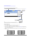
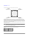
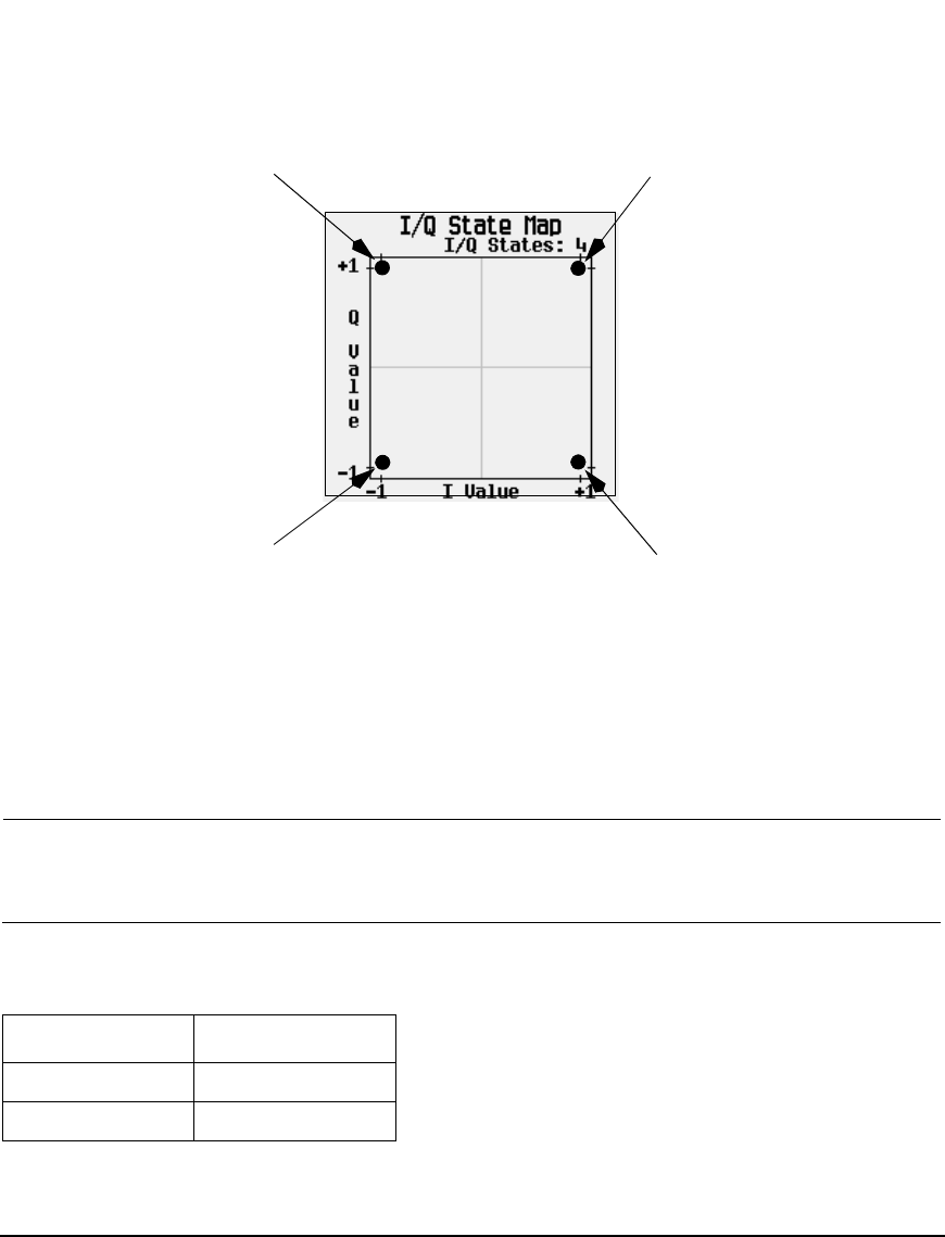
The following illustration shows a 4QAM modulation I/Q State Map.
Differential encoding employs relative offsets between the states in the symbol table to encode
user–defined modulation schemes. The Differential State Map table editor is used to introduce
symbol table offset values which in turn cause transitions through the I/Q State Map based on their
associated data value. Whenever a data value is modulated, the offset value stored in the Differential
State Map is used to encode the data by transitioning through the I/Q State Map in a direction and
distance defined by the symbol table offset value.
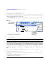
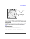
Entering a value of +1 will cause a 1–state forward transition through the I/Q State Map, as shown
in the following illustration.
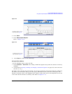
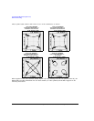
NOTE The following I/Q State Map illustrations show all of the possible state transitions using a
particular symbol table offset value. The actual state–to–state transition would depend upon
the state in which the modulation had started.
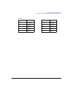
As an example, consider the following data/symbol table offset values.
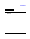
Table 11-2
Data Offset Value
00000000 +1
00000001 –1
1st Symbol
Distinct values: +1, +1
Data = 00000000
2nd Symbol
Distinct values: –1, +1
Data = 00000001
4th Symbol
Distinct values: +1, –1
Data = 00000011
3rd Symbol
Distinct values: –1, –1
Data = 00000010
1
2
3
4


