


Page: 20 Model MX88
© 2011 Xantech Corporation
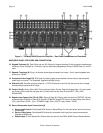
PREAMP OUT
Each zone has a Preamp Out to send „zone selected‟ audio to an outboard power amplifier such as the
Xantech PA4100x. This may be needed for powering a sub-zone, or for use in zones that require more than
50W a channel, or for sending audio to another amplifier with Dolby™ surround decoding for „theater
quality‟ audio in that zone.
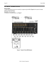
Using good quality RCA-type patch cables, connect the Preamp Out, Left (L) and Right (R) connectors –
Figure 3 item 25, to the desired external amplifiers Audio Left and Right Input connectors.
CO1 AND CO2 (ZONES 7 & 8)
Zones 7 and 8 have a Remote Mute/Standby output for interfacing and controlling an external power
amplifier, such as the higher powered PA4100x. The control is provided via a Stereo Mini Jack with the “tip”
of the mini-phone connector controlling “standby” logic (Power On = +12VDC, Power Off = 0VDC) and the
“ring” controlling “mute” logic (Mute = +12VDC, Un-Mute = 0VDC).
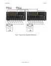
Using a 3.5mm stereo mini Jack to 3.5mm stereo mini Jack cable, plug one end into the CO1 (or CO2)
output jack on the rear of the MX88 Controller/Amplifier – Figure 3 item 21 and the other end into the
corresponding jack labeled CO1 (or CO2) on the Xantech power amplifier.
NOTE: If using a Xantech PA4100X amplifier, be sure to set the Control In (CI) switch to ON located on the
rear panel of the amp.
ZONE IR
Using Xantech emitters (282D, 283D,284D, 286D, etc.), plug the 3.5mm mono mini jack into the
appropriate zones Zone IR connector – Figure 3 item 28. Affix the emitter side to the desired zone related
component you wish to control. If more than one device needs to be controlled, use a mono mini to
stripped-ends wire (p/n 6015900) wired to a Xantech 791-44 Amplified Connecting block. Any IR from the
zone (generated by the touch-panel, received at the keypad or touch-panel and passed through, or routed
from another zone (set up via Universal Dragon only) will be outputted from this emitter port.
AC POWER CONNECTIONS
Use one of the supplied AC power cords specific to your region or country, insert it into the AC inlet on the
back panel of the MX88, and plug into a power source capable of delivering the rated current and power
stated on the back panel of the MX88.
CONNECTIONS AT THE ZONE LOCATION
KEYPAD CONNECTIONS AND JUMPER SETTINGS
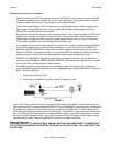
Single Keypad CAT5 Connections
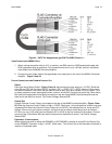
1. Refer to Figure 4 for proper termination at the zone-end of the CAT5 cable.
2. Set Keypad Address, using specific instructions provided in the manual for that specific keypad.
2. Connect the CAT5 cable from the MX88 Controller/Amplifier into the RJ45 jack marked “Controller” on
the rear of the MX88 keypad.
Caution: Power voltage for the keypad is transmitted along this cable! Incorrect wiring on this cable can
destroy the keypad or touch-panel! Be sure to test cable for proper connections before making connections.
Multiple Keypad Connections
1. For a second keypad in the same zone, terminate the CAT5 cable in the same way as shown in Figure
4.
2. Connect the CAT5 coming from the MX88 Controller to the “CONTROLLER” jack on the Primary
Keypad. Plug a CAT5 cable into the “EXPANSION” jack on the Primary Keypad and connect it to the