


10
.
www.velodyne.com
Digital Drive User’s Manual
4
. Connect the audio/video cables between your SMS
-1
(EQ OUTPUT VIDEO/LEFT/RIGHT
–
yellow, white, and red respectively) and your electronics (receiver, processor, TV, etc.). Insert
t
he color
-c
oded cable plugs into the correct EQ OUTPUT receptacle
– t
he yellow plug into the
VIDEO jack, the white plug into the LEFT jack, and the red plug into the RIGHT jack. The
opposite ends of the cables should be connected to your receiver/processor. The yellow
VIDEO cable goes to an available composite video input (e.g. aux), and the white/red AUDIO
(L&R) cables go to a corresponding audio input. As an alternative to composite video, you
may want to use S
-video (S-video connector not included). Connect the S-video from the
SMS
-1 to an S-video compatible input on either your processor or TV. Consult your
receiver/processor and/or TV owner’s manual for more information.
5. Connect your subwoofer(s) to the SMS
-1 using the XLR connector or LFE out RCA connector.
6. Defeat the crossover on your subwoofer(s) (if possible) and set its volume to the
middle setting.
NOTE: Make sure the audio output goes into your AUDIO system, not your TV! The SMS
-1 will
generate test tones used to match the SMS
-1 to your satellites and to correct for room
anomalies that need to be played by your main audio system.
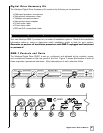
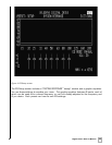
7. Insert the XLR microphone cable’s 3
-pin male plug into the MIC INPUT jack (location 7 on
Figure 2) on the front or back panel of the SMS
-1.
8. Slide the microphone (male connector end first) down through the open, circular sleeve of
the tabletop microphone stand. Position this assembly at a desired listening position.
NOTE: The Digital Drive Accessory Kit includes a microphone stand adapter (1/2”
-27 thread)
for use with pr
ofessional mounting stands. Be sure to first remove the inner thread piece
(3/8”
-16) before using.
9. Connect the XLR micr
ophone cable’
s female jack end with the male connector end of the
microphone.
10. Sheath the microphone pickup with the foam windscreen cover as a protection against dirt
and airborne contaminants.
A Word About Interconnect Cables
When installing your new Velodyne SMS-1 using the line level connections, you should always
use shielded phono cables. Ther
e ar
e many quality cables available today
, most any of which
will work per
fectly well. We do recommend that you keep the length of cable as short as
possible to avoid any potential noise problems.
A Word About Connecting more than one SMS- 1
Note that your SMS-1 can control up to three subwoofers. Each of the three subwoofers will
receive the same conditioned signal fr
om the SMS
-1. If you wish to r
un mor
e then three
subwoofers, or wish to individually customize the signal to different subwoofers, you will need
more than one SMS
-1 connected in a “daisy-chain” configuration. This section describes setup
in a daisy
-chain configuration.