


Installation– Step-By-Step
9
.
www.velodyne.com
Digital Drive User’s Manual
T
o ensure a quick and flawless installation of your Velodyne Digital Drive SMS
-1
, follow these
setup instructions.
SMS-1 Cable Connections
Make all necessary cable connections between the applicable SMS-1 connector port and your
particular home electronics equipment in the following order:
1. Insert the detachable power supply into the power interface port on the rear panel of your
SMS
-1. Plug the male end of the cord into a convenient wall outlet.
2. Provide signal to your SMS
-1 through one or more of the following connections (refer to your
receiver/processor owner’s manual for available inputs to the SMS
-1):
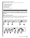
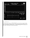
a. LFE INPUT (RCA, the RED jack at location 17 on Figure 1)
– This is the most common
input cable connection. Make a connection between this input and the LFE output of
your receiver or processor; OR
b. LFE INPUT (XLR, location 7 on Figure 1)
– Make a connection between this input and
the balanced LFE outputs of your receiver or processor; OR
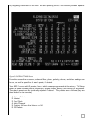
c.
INPUT, LEFT and RIGHT (location 17 on Figure 2)
– Make a connection between these
inputs and the stereo outputs of your receiver or processor; OR
d. SPEAKER
-LEVEL INPUT (location 18 on Figure 2) - Make a connection between these
inputs and the left and right speaker connections on your receiver or pr
ocessor.
Make this connection by inserting speaker wire into the correct terminals of the
ter
minal block.
3. Establish the return line
-level connection (optional). Connect to a pre-amplifier’s main outputs
and return them to your amplifier inputs. When installed in this fashion, your satellite
speakers will be crossed over at 80Hz, which removes the lower bass from your amplifier
and speakers, enabling them to do a better job reproducing high frequencies. By utilizing
this method, you will have a bi
-amplified system, gaining impr
oved power and headr
oom for
your system.
NOTE: To bypass the 80Hz crossover described in step 3, use the THRU output jacks instead
of the OUTPUT jacks.
A word about SMS-1 outputs
The Velodyne SMS-1 is designed to operate using the full range audio signal for input when using
the digital built
-in cr
ossover
. Most pr
ocessors/receivers have a “subwoofer out” or LFE jack
that is inter
nally filtered and designed to be used with a conventional amplifier and speaker. In
some rare cases, combining both an external crossover and the one internal to the SMS
-1 may
result in low output and increased noise. In these installations you may need to bypass the
internal crossover in either the processor or Velodyne SMS
-1. In some installations, simply
setting one crossover to a higher frequency (such as 120Hz) will restore maximum
performance. To bypass the SMS
-1’s internal crossover when the unit is being fed a low pass
signal from another cr
ossover
, r
efer to the SETUP instructions at step 14, below.
Note: If not using an exter
nal crossover, you should use the built
-in cr
ossover for
optimal performance.