


6
.
www.velodyne.com
Digital Drive User’s Manual
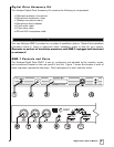
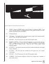
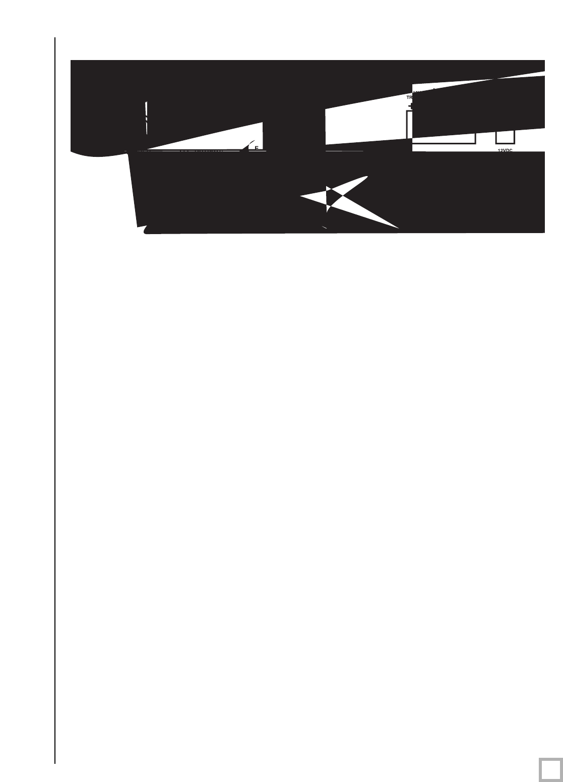
Figure 2: Digital Drive Front and Rear Panel Connections
(1)
POWER
– Pr
ess the POWER switch to the ON position to activate the SMS
-1. If the
unit is to be left unused for an extended period of time, press the switch to the OFF
position to prolong the life of the SMS
-1.
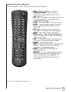
(2) IR Remote Sensor.
(3) LCD Display – This display shows subwoofer volume, preset, and indicates auto-EQ,
self
- EQ, mute, and night mode operation.
(4) MIC INPUT
– This XLR input jack is for the XLR microphone cable.
(5) VOLUME UP/DOWN
– Press the black UP pushbutton to incrementally raise your
SMS
-1’s system volume; press the black DOWN pushbutton to incrementally
lower your SMS
-1’s system volume. Note the use of these buttons during
software updates.
(6) LFE OUTPUT
– This balanced connector sends the conditioned subwoofer audio signal
to your subwoofer
.
(7) LFE INPUT
– This XLR input jack receives the LFE signal from your receiver
or processor.
(8) MIC INPUT
– This XLR input jack is for the XLR microphone cable.
(9) IR REMOTE
– This connection allows for hook-up of an IR signal fr
om a r
epeater or
other similar device.