


7
.
www.velodyne.com
Digital Drive User’s Manual
(
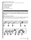
10) RS
-2
32 OUT
– U
se this port to communicate with a second “daisy
-c
hained” Digital
Drive SMS
-1.
(11) RS
-232 IN – Use this port to communicate with your computer (for software
updates), a touch panel remote control, or another upstream Digital Drive SMS
-1.
See Appendix A for an explanation of the use of the serial port, available commands,
and their formats.
(12) EQ Video Output
– Used to display the video generated by the SMS-1. S-Video or
composite connections are available. A composite video cable is included. NOTE:
Only connect to a single video output at a time.
(13) LFE OUTPUT – These connectors send the conditioned subwoofer audio signal to up
to three subwoofers.
(14) EQ OUTPUT LEFT/RIGHT
– Connect the audio cable from your accessory kit to these
jacks: white plug to LEFT, and red plug to RIGHT.
(15) THRU
– These RCA connectors are for sharing the same signal that goes into your
SMS
-1 with a second “daisy-chained” SMS-1 or other device. Unaltered line-level
signal comes out of the THRU jack.
(16)
OUTPUT
– These RCA connectors incorporate the use of an 80Hz 6 dB/octave slope
high pass crossover.
(17) INPUT LFE
– These RCA input jacks are for line-level connection.
(18)
12V TRIGGER/SPEAKER LEVEL INPUT RIGHT/LEFT
– If the 12 volt trigger mode is
active, 12 volts is required across these pins for power to be activated. The speaker
-
level connector allows for connection with exposed speaker wire.
(19) 12V DC POWER SUPPLY INPUT
- Connect the power supply to this jack.