


Velodyne Digital Drive User’s Manual Page 18
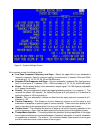
Note that displaying the System Response screen by using the TEST button from the System Settings
screen ONLY allows you to view the system response - you cannot make any changes to EQs or
volume. Press TEST again to return to the System Settings screen.
NOTE: To bypass the low pass crossover, set the frequency to 199Hz.
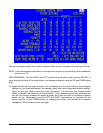
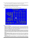
15. Now adjust the low pass crossover slope. This setting is shipped at 24 dB/octave – a fairly steep
slope to prevent the subwoofer from playing upper frequencies that might call attention to it during
normal operation. At this stage, set the crossover settings under the column entitled SETUP.
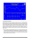
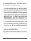
Reduce the slope if necessary and use the BACK button to return to the EQ setup screen and
observe the “system response” graph – it should be as flat as possible at the crossover frequency
and immediately to the left and right of it. Too gradual a slope (e.g. 6 dB/octave) may produce a
bump at the crossover frequency, and too steep a slope may produce a dip.
16. You should normally not need to adjust the subsonic filter. Do so only if there are anomalies in the
very lowest frequencies that you cannot address using the normal EQ process as described below.
17. Next, adjust the phase and polarity settings (if needed). Phase is in effect a short delay in the
reproduction of the audio signal. The polarity reverses the phase (i.e. 180
o
shift). Adjusting phase
can change the dynamics of standing waves and black holes in the room. Sometimes it may be
useful to adjust the phase if there is a particularly difficult peak or valley to eliminate, and/or your
room placement options are limited. Phase and polarity are also important tools to match your
subwoofer to your main speakers. You will often see a dip or peak in the crossover frequency
between your subwoofer and main speakers. Rather than correcting this dip with an EQ, try
adjusting the phase and polarity settings. It is very common for the main speakers to interact with
the subwoofer to diminish or accent frequencies near the crossover point (since this is the point
where both the subwoofer and the speakers are playing the same audio information). Don’t be
afraid to experiment to find the perfect match between your subwoofer and main speakers!
NOTE: The following step shows using the graphic equalizer (using fixed frequencies and Q) to equalize
the room.
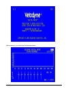
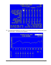
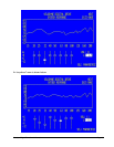
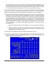
18. Next, return to the EQ setup screen and adjust the graphical EQs to eliminate peaks and valleys
from the room response. Use the right and left arrow keys to position the cursor over the EQ you
wish to adjust. If you see a peak in the response at, say, 25Hz (this would be evident in the
“SYSTEM RESPONSE” graph), simply navigate the cursor to the EQ that corresponds to 25Hz
and use the up or down arrow keys to “slide” the EQ up or down. An example of this is shown on
the next page.
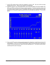
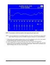
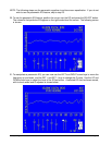
19. Continue this process until the system response graph shows a +/-3dB response across the bass
frequencies (that is, up to about 120Hz.). Note that this does not necessarily mean a “ruler flat”
response; +/-3dB is typical for an optimized response curve.
NOTE: Phase and polarity may be useful in eliminating particularly stubborn peaks and valleys. Phase
is in effect a short delay in the creation of the signal, and adjusting phase can change the dynamics of
standing waves and black holes in the room. Sometimes it may be useful to adjust the phase if there
is a particularly difficult peak or valley to eliminate, and/or your room placement options are limited.