


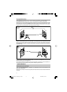
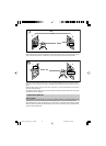
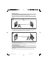

Adjusting in Parallel
In order to measure irregularities, create right angles, align partitions in right angles or to mark vertical lines,
the direct beam (plumb beam) has to be adjusted parallel which means the laser beam has to be placed in the
same offset distance to a wall or any other reference line.
Therefore place and align the unit in vertical mode, so that the beam runs roughly in parallel to a wall or other
reference line. Measure the distance between the beam and the wall near the unit and at a certain distance.
To adjust the beam in parallel, press the line button 4 or 5 to realize the same offset distance at the unit and far
away.
The procedure for aligning an extension joint is similar. Just position the unit so that the beam runs directly
above the joint.
A long reference distance is important for accuracy. Therefore it should be as long as possible.
Right Angles/Vertical Mode
Set up the unit in vertical mode so that the perpendicular beam is parallel to a reference line (e.g. a wall). The
rotating laser beam is now at a right angle from your original point and as a vertical area available.
The best visibility is reached by using the line mode (e.g. as a perpendicular).
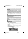
Transferring marks to the Ceiling - Plumb Point
The origin of the laser beam is located directly above the horizontal tripod mount and the height of the vertical
tripod mount.
In order to transfer a marked point from the bottom to the ceiling, there are center marks 13 at the lower part of
the unit's housing. Using these marks, the unit may be set up with the two axes X and Y above two crossed chalk
marks, for example.
For better installation of the unit above a mark on the floor, just mark 2 rectangular lines through this
point.
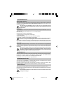
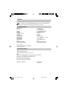
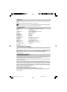
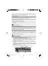
WALL MOUNT M300 (optional)
1. Nail Hole – allows you to hang the wall mount onto a nail or screw.
2. Locking Lever – opens/closes the clamp.
3. Stop Screw - stops the sliding bracket from moving beyond a set point on the wall mount. The screw can
be moved so that the center of the beam aligns with the wall molding 0.0 cm (0.0 in.) or (3.1 cm (1 ˘ in.)
4. 5/8" –11 Laser Mount – lets you connect the laser to the wall mount and holds the sliding bracket in place
after it has been positioned along the elevation scale.
5. Reading Edge – allows you to adjust the laser position appropriate for your application needs.
6. 5/8"-11 Tripod Mount – lets you connect the wall mount to a standard tripod when using in vertical mode.
7. Elevation Scale – provides graduated marks that indicate the position of the laser relative to the wall-
molding height. The adjustment range on the scale is from 3.1 cm (1 ˘ in.) above wall-molding height to
5 cm (2 in.) below it. (The „–2“ position is aligned with the horizontal centerline at the ceiling target.)
8. Lock Nut – lets you adjust the clamping force.
9. Clamp – opens/closes so that the wall mount can be attached to wall molding or floor track.
1
2
3
4
5
6
7
8
9
031266_02_apollo_eng_12-18.p65 29.08.2003, 10:29 Uhr16