15
[Changing the input and output meter display status]
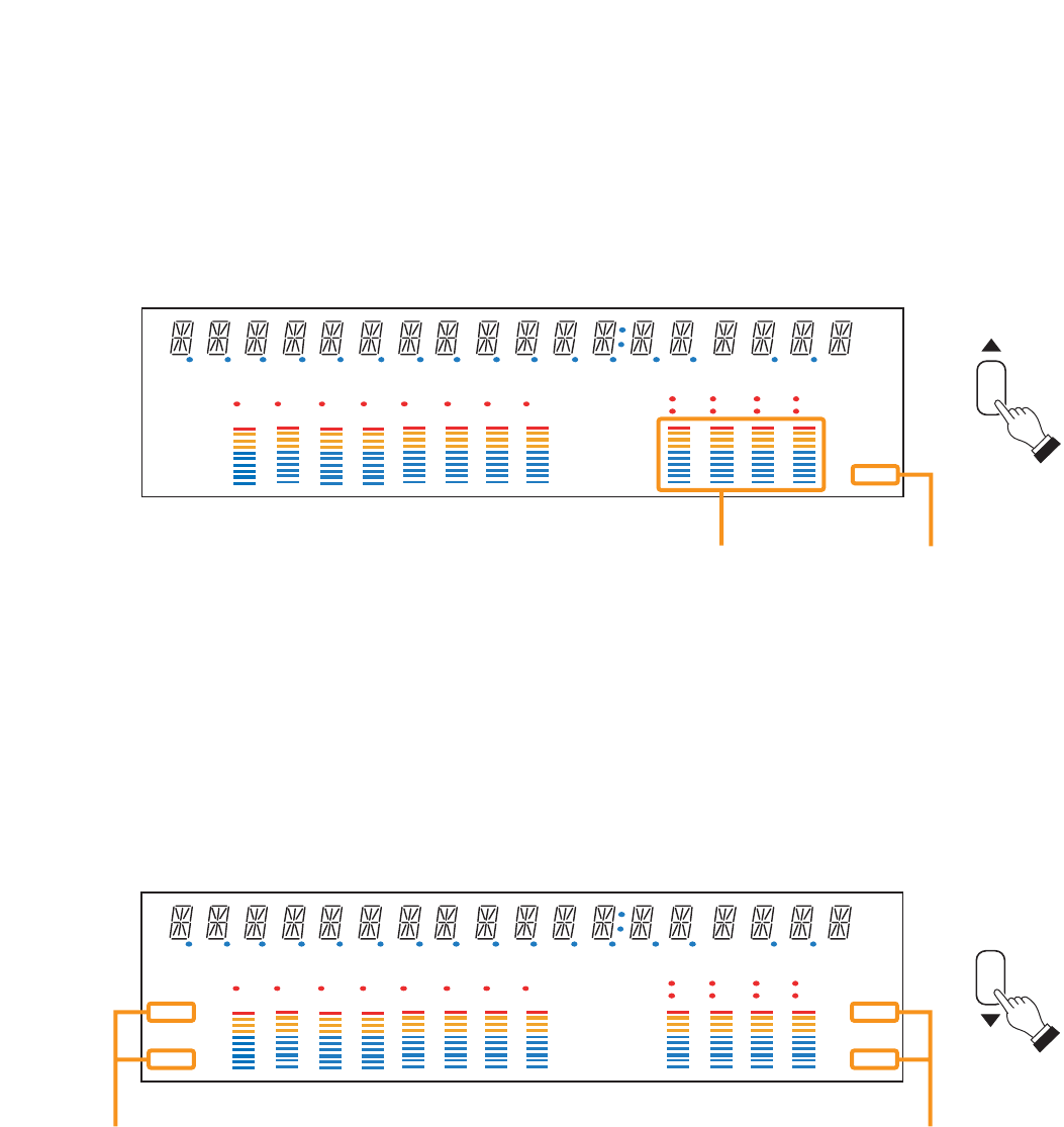
When the input or output gain setting screen is displayed, pressing the Down shift key alternately switches the
input and output meter display status between the signal level and the fader position.
The LEVEL indicators on both input and output meters light when the signal levels are indicated, while the
FADER indicators light when the fader positions are indicated.
d B
kHz
m sec
COM
FAULT
KEYLOCK
EMERGENCY
EQ
COMP
GATE
DELAY
DUCK
NOM
LOUD
TONE
GAIN dB FREQQ
OL
0
–10
–20
–30
–40
OL
0
–10
–20
–30
–40
FADER
LEVEL
FADER
LEVEL
12345678
1234
5678
Input meter status indicator Output meter status indicator
Note: The figure above is the VFD screen display when the input and output levels are indicated.
[Changing the indicated channels on the LEVEL output meter]
The output meter indicates the signal levels of only a set of 4 channels: CH 1 – 4 (factory-preset) or CH 5 – 8.
When the input or output gain setting screen is displayed, pressing the Up shift key alternately switches the
level indication between CH 1 – 4 and CH 5 – 8.
The LEVEL indicator of the output meter status indicator flashes while the CH 5 – 8 are indicated, and stays lit
while the CH 1 – 4 are indicated.
In the same manner, the output meter also changes in the Fader indication.
d B
kHz
m sec
COM
FAULT
KEYLOCK
EMERGENCY
EQ
COMP
GATE
DELAY
DUCK
NOM
LOUD
TONE
GAIN dB FREQQ
OL
0
–10
–20
–30
–40
OL
0
–10
–20
–30
–40
FADER
LEVEL
FADER
LEVEL
12345678
1234
5678
Output meter Output meter status indicator


