


– 54 –
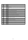
Pin No. Pin Name I/O Function
49 SQOUT I
Subcode Q data input from the DSP (IC102)
50 COIN O
Command serial data output to the RF amplifier (IC101) and DSP (IC102)
51 SCLK O
Serial data transfer clock signal output to the CD text decoder (IC104) “L” active
52 SRDT I
Serial data input from the CD text decoder (IC104)
53 NC O
Not used (open)
54 DRF I
Focus OK signal input from the RF amplifier (IC101) and DSP (IC102) “L”: NG, “H”: OK
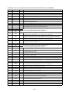
55 WRQ I
Subcode Q synchronizing signal input from the DSP (IC102) “H” active
56 RMIN I
Remote control signal input from the remote control receiver (IC902) “L” active
57 TGL I
Tracking gain control signal input from the DSP (IC102)
Gain becomes low when tracking gain is “H”
58 RWC O
Command latch output to the RF amplifier (IC101) and DSP (IC102) “L” active
59 SL– O
Sled feeding signal (internal direction) output to the RF amplifier (IC101) “H” active
60 DQSY I
Serial data synchronizing signal input from the CD text decoder (IC104) “L” active
61 XMODE O
Reset signal output to the CD text decoder (IC104) “H”: reset
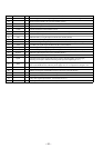
62 T.SENS1 I
Disc table flag detect sensor (IC51) input terminal
63 T.SENS2 I
Disc table flag detect sensor (IC52) input terminal
64 T.SENS3 I
Disc table home position detect sensor (IC53) input terminal
65 DOWNSW I
Inputs the loading out switch (S52) detection signal “L” active
66 UPSW I
Inputs the loading in switch (S51) detection signal “L” active
67 SELECT I
Not used (fixed at “H”)
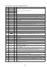
68 to 71 D3 to D6 I/O
Two-way data bus with the static RAM (IC502)
72 VDD —
Power supply terminal (+5V)
73 NC (VDD) —
Not used (connected to power supply (+5V) line)
74 D7 I/O
Two-way data bus with the static RAM (IC502)
75 to 77 D0 to D2 I/O
Two-way data bus with the static RAM (IC502)
78 to 80 A0 to A2 O
Address signal output to the static RAM (IC502)