


– 52 –
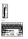
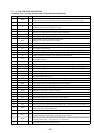
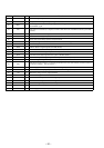
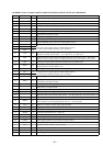
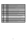
Pin No. Pin Name I/O Function
42
MUTER O
Line muting on/off control signal output terminal (for R-ch side) “H”: muting on
43
XVDD —
Power supply terminal (+5V) (crystal oscillator system)
44
XOUT O
System clock output terminal (16.9344 MHz)
45
XIN I
System clock input terminal (16.9344 MHz)
46
XVSS —
Ground terminal (crystal oscillator system)
47
SBSY O
C1, C2, single correction, and double correction monitor output to the CD text decoder (IC104)
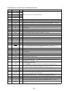
48
EFLG O
Subcode P to W output terminal
49
PW O
Subcode frame sync signal output to the CD text decoder (IC104)
50
SFSY O
Write frame clock signal output to the CD text decoder (IC104)
51
SBCK I
Subcode reading clock signal input from the CD text decoder (IC104) (schmitt input)
52
FSX O
7.35 kHz sync signal output divided from the crystal oscillation
53
WRQ O
Subcode Q synchronizing signal output to the system controller (IC501)
54
RWC I
Command chip enable signal input from the system controller (IC501) (schmitt input)
55
SQOUT O
Subcode Q data output to the system controller (IC501)
56
COIN I
Command serial data input from the system controller (IC501)
57
CQCK I
Command serial clock signal input from the system controller (IC501) (schmitt input)
Fetching clock input or subcode extracting clock input from SQOUT (pin %∞)
58
RES I
System reset signal input from the reset signal generator (IC201) “L”: reset
For several hundreds msec. after the power supply rises, “L” is input, then it changes to “H”
59
TEST11 O
Test output terminal Not used (open)
60
16M O
Master clock signal (16.9344 MHz) output to the CD text decoder (IC104)
61
4.2M O
Reference clock signal (4.2336 MHz) output to the RF amplifier (IC102)
62
TEST5 I
Test input terminal (fixed at “L” in this set)
63
CS I
Chip select signal input terminal Not used (fixed at “L”)
64
TEST1 I
Test input terminal (fixed at “L” in this set)