


– 53 –
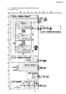
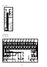
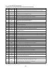
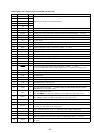
• MAIN BOARD IC501 CXP84340-071Q (SYSTEM CONTROLLER)
Pin No. Pin Name I/O Function
1 to 5 A3 to A7 O
6 A12 O
7 A14 O
Address signal output to the static RAM (IC502)
8 to 11 A11 to A8 O
12 A13 O
13 WE O
Data write enable signal output to the static RAM (IC502) “L” active
14 LDIN O
Loading motor drive signal (load-in direction) output to the BA6780 (IC601) “H” active
15 LDOUT O
Loading motor drive signal (load-out direction) output to the BA6780 (IC601) “H” active
16 TBLL O
Table motor drive signal (counterclockwise) output to the BA6780 (IC601) “H” active
17 TBLR O
Table motor drive signal (clockwise) output to the BA6780 (IC601) “H” active
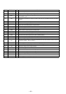
18, 19 NC O
Not used (open)
20 HHOUT O
AND output of T.SENS1 (pin ^™) and T.SENS2 (pin ^£) when the test mode
21 LEDL O
Serial data latch pulse output to the LED driver (IC903) “H” active
22 FLLT O
Serial data latch pulse output to the FL driver (IC901) “L” active
23 JOG1 I
Jog dial pulse input from the rotary encoder (RE901)
24 JOG2 I
Jog dial pulse input from the rotary encoder (RE901)
25 DOORSW I
Door open/close detect switch (S925) input “L”: close, “H”: open
26 FLCK O
Serial data transfer clock signal output to the FL driver (IC901) “L” active
27 FLDT O
Serial data output to the FL driver (IC901)
28 ZMUTE O
Muting on/off control signal output for the 2nd CD IN “H” active
29 ICSW O
Enable signal output to the LA5602 (IC201) Used for the BD section reset “H” active
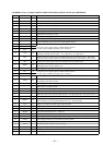
30 RESET I
System reset signal input from the reset signal generator (IC203) “L”: reset
For several hundreds msec. after the power supply rises, “L” is input, then it changes to “H”
31 EXTAL I
Main system clock input terminal (10 MHz)
32 XTAL O
Main system clock output terminal (10 MHz)
33 VSS —
Ground terminal
34 TX O
Sub system clock output terminal Not used (open)
35 TEX I
Sub system clock input terminal Not used (fixed at “L”)
36 AVSS —
Ground terminal (for A/D converter)
37 AVREF I
Reference voltage (+5V) input terminal (for A/D converter)
38 KEY0 I
Key input terminal (A/D input) CLEAR, CHECK, FADER, MEMO SEARCH, INPUT,
TIME/TEXT keys input (S901 to 906)
39 KEY1 I
Key input terminal (A/D input)
±, ≠, p, P, ·, PLUS ONE, REPEAT, PLAY MODE keys input (S907 to 914)
40 KEY2 I
Key input terminal (A/D input)
I/u, X-FADE, NO DELAY, MEGA CONTROL keys input (S921 to 924)
41 KEY3 I
Key input terminal (A/D input) GROUP 5 to 1, GROUP FILE keys input (S915 to 920)
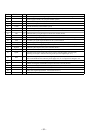
42 D.SENS I
Inputs the disc sensor (Q51) detection signal “H” active
43 CD1/2/3 I
COMMAND MODE switch (S701) input terminal
“L”: CD1, “H”: CD3 (CD2: center voltage input)
44 TEST I
Setting terminal for the test mode “L”: ADJ mode, center voltage: AFADJ mode
45 BUSOUT O
Sircs remote control signal output for the S-LINK CONTROL A1 “H” active
46 BUSIN I
Sircs remote control signal input for the S-LINK CONTROL A1 “L” active
47 SL+ O
Sled feeding signal (external direction) output to the RF amplifier (IC101) “H” active
48 CQCK O
Command serial clock signal output to the RF amplifier (IC101) and DSP (IC102)
“L” active