


– 50 –
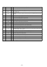
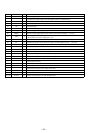
Pin No. Pin Name I/O Function
40
CV+ I
CLV error signal input from the DSP (IC102)
41
RFSM O
Playback EFM RF signal output to the DSP (IC102)
42
RFS– I
Works together with the RFSM (pin $¡) to set the RF gain and the 3T compensation constant for
the EFM RF signal
43
SLC O
SLI (Slice Level Control) is output to control a data slice level of the RF waveform by the DSP
(IC102)
44
SLI I
Input terminal for controlling a data slice level by the DSP (IC102)
45
DGND —
Ground terminal (digital system)
46
FSC O
Focus search smoothing capacitor output terminal
47
TBC I
TBC (Tracking Balance Control) sets a EF balance variable range
48
NC —
Not used (open)
49
DEF O
Defect detection signal output to the DSP (IC102)
50
CLK I
Reference clock (4.2336 MHz) input from the DSP (IC102)
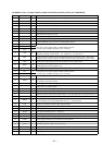
51
CL I
Command serial clock signal input from the system controller (IC501)
52
DAT I
Command serial data input from the system controller (IC501)
53
CE I
Command chip enable signal input from the system controller (IC501)
54
DRF O
Focus OK signal output to the system controller (IC501) “L”: NG, “H”: OK
55
FSS I
FSS (Focus Search Select) is a switching terminal for the focus search mode (±search/+search for
a reference voltage) Not used (open)
56
VCC2 —
Power supply terminal (+5V) (servo system and digital system)
57
REFI I
Connected to the coupling capacitor for the reference voltage (+2.5V)
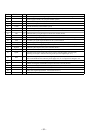
58
VR O
Reference voltage (+2.5V) output terminal
59
LF2 I
Constant setting for a disc defect detection
60
PH1 I
Connected to the capacitor for the RF signal peak hold
61
BH1 I
Connected to the capacitor for the RF signal bottom hold
62
LDD O
Laser drive signal output to the automatic power control circuit
63
LDS I
Light amount monitor input of the laser diode (PD)
64
VCC1 —
Power supply terminal (+5V) (RF system)