


– 49 –
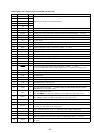
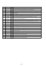
7-12. IC PIN FUNCTION DESCRIPTION
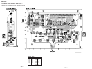
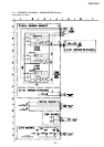
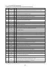
• BD BOARD IC101 LA9241M (RF AMPLIFIER, FOCUS/TRACKING/SLED SERVO)
Pin No. Pin Name I/O Function
1 FIN2 I
Signal input (B+D) from the optical pick-up detector
Added with FIN1 to create RF signal, subtracted with FIN1 to create focus error signal
2
FIN1 I
Signal input (A+C) from the optical pick-up detector
3EI
Signal input (E) from the optical pick-up detector
Subtracted with F to create tracking error signal
4FI
Signal input (F) from the optical pick-up detector
5TBI
Tracking error signal input for the tracking balance adjustment
6 TE– I
Tracking error signal (invert signal) input terminal
7TEO
Tracking error signal output terminal
8 TESI I
TES (Track Error Sense) comparator input terminal
Tracking error signal is band-passed and input
9 SCI I
Shock detection input terminal
10 TH I
Time constant setting terminal for the tracking gain adjustment
11 TA O
TA amplifier output terminal
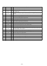
12 TD– I
Creates a tracking phase compensation constant between TD (pin !£) and VR (pin %•) pins
13 TD O
Setting terminal for the tracking phase compensation
14 JP I
Setting terminal for the tracking jump signal (kick pulse) amplitude
15 TO O
Tracking coil (2-axis device) drive signal output to the LA6541 (IC103), and sled motor drive
signal output terminal
16 FD O
Focus coil (2-axis device) drive signal output to the LA6541 (IC103)
17 FD– I
Creates a focusing phase compensation constant between FD (pin !§) and FA (pin !•) pins
18 FA O
Creates a focusing phase compensation constant between FD– (pin !¶) and FA– (pin !ª) pins
19 FA– I
Creates a focusing phase compensation constant between FA (pin !•) and FE (pin @º) pins
20 FE O
Focus error signal output terminal
21 FE– I
Focus error signal (invert signal) input terminal
22 AGND —
Ground terminal (analog system)
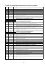
23 SP O
Single end output of the CV+ (pin $º) and CV– (pin #ª) pins signal
24 SPI I
Spindle amplifier input terminal (invert input)
25 SPG I
Gain setting resistor is connected when the spindle 12 cm mode
26
SP– I
Works together with the SPD (pin @¶) to connect to the spindle phase compensation constant
27
SPD O
Spindle motor (M101) drive signal output to the LA6541 (IC103)
28
SLEQ I
Sled phase compensation constant is connected
29
SLD O
Sled motor (M102) drive signal output to the LA6541 (IC103)
30
SL– I
Sled feeding signal input from the system controller (IC501)
31
SL+ I
Sled feeding signal input from the system controller (IC501)
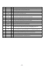
32
JP– I
Tracking jump control signal input from the DSP (IC102)
33
JP+ I
Tracking jump control signal input from the DSP (IC102)
34
TGL I
Tracking gain control signal input from the DSP (IC102) Gain becomes low when TGL is “H”
35
TOFF I
Tracking off control signal input from the DSP (IC102)
Tracking becomes off when TOFF is “H”
36
TES O
Tracking error signal output to the DSP (IC102)
37
HFL O
Tracking detection signal output to the DSP (IC102) HFL (High Frequency Level) is used to
determine whether the main beam is positioned on a pit or a mirror
38
SLOF I
Sled servo off control signal input from the DSP (IC102) Rough servo/phase control automatic
switching monitor input “H”: rough servo, “L”: phase servo
39
CV– I
CLV error signal input from the DSP (IC102)