


– 17 –
SECTION 6
ELECTRICAL ADJUSTMENTS
Note :
1. CD Block is basically designed to operate without adjustment. There-
fore, check each item in order given.
2. Use YEDS-18 disc (3-702-101-01) unless otherwise indicated.
3. Use an oscilloscope with more than 10MΩ impedance.
4. Clean the object lens by an applicator with neutral detergent when the
signal level is low than specified value with the following checks.
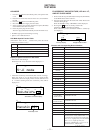
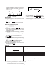
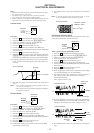
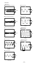
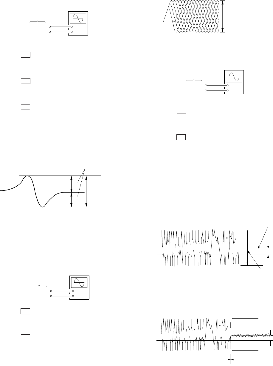
S Curve Check
11. Turn OFF the power, and remove the lead wire connected at
step 7.
Note : A clear RF signal waveform means that the shape “◊” can be
clearly distinguished at the center of the waveform.
Procedure :
1. Press the I/u button and turn ON the power supply.
2. Open the front cover, and press the
[PLUSONE] button.
3. Set the disc (YEDS-18) into the “PLUS ONE” slit.
4. Close the front cover, and chuck the disc.
5. Press the I/u button and turn OFF the power.
6. Connect the oscilloscope to TP (FE) of the BD board.
7. Connect TP (ADJ) of the MAIN board and connect TP (GND)
with a lead wire.
8. Press the I/u button and turn ON the power.
9. The first track will be played back automatically. When the
[CHECK] button is pressed, “S-JI mode” will be displayed on
the fluorescent indicator tube, and focus search will be repeated.
10. Check the oscilloscope waveform (S-curve) is symmetrical be-
tween A and B. And confirm peak to peak level within 1.8 ±
0.6 Vp-p.
11. Turn OFF the power, and remove the lead wire connected at
step 7.
Note : • Try to measure several times to make sure than the ratio of A
: B or B : A is more than 10 : 7.
• Take sweep time as long as possible and light up the brightness
to obtain best waveform.
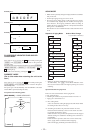
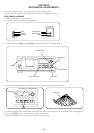
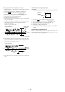
RF Level Check
Procedure :
1. Press the I/
u button and turn ON the power supply.
2. Open the front cover, and press the [PLUSONE] button.
3. Set the disc (YEDS-18) into the “PLUS ONE” slit.
4. Close the front cover, and chuck the disc.
5. Press the I/u button and turn OFF the power.
6. Connect the oscilloscope to TP (RF) of the BD board.
7. Connect TP (ADJ) of the MAIN board and connect TP (GND)
with a lead wire.
8. Press the I/u button and turn ON the power.
9. Playback the fifth track of the disc.
10. Confirm that oscilloscope waveform is clear and check RF
signal level is correct or not.
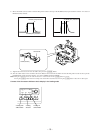
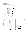
E-F Balance (Traverse) Check
The procedure for this checking method differs for when a gen-
eral remote control unit is used and not used.
When a general remote commander is used:
1. Press the I/u button and turn ON the power supply.
2. Open the front cover, and press the
[PLUSONE] button.
3. Set the disc (YEDS-18) into the “PLUS ONE” slit.
4. Close the front cover, and chuck the disc.
5. Press the I/u button and turn OFF the power.
6. Connect the oscilloscope to TP (TE) of the BD board.
7. Connect TP (ADJ) of the MAIN board and connect TP (GND)
with a lead wire.
8. Press the I/u button and turn ON the power.
9. Playback the fifth track of the disc.
10. Press the
[3] button on the remote commander. (The tracking
servo and the sledding servo are turned OFF.)
11. Check the level B of the oscilliscope's waveform and the A
(DC voltage) of the center of the Traverse waveform.
Confirm the following :
A/B x 100 = less than ± 10%
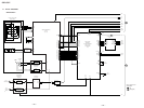
BD board
TP (FE)
TP (VC)
+
–
oscilloscope
symmetry
S-curve waveform
within 1.8
±
0.6 Vp-p
A
B
BD board
TP (RF)
TP (VC)
+
–
oscilloscope
(AC range)
level: 1.8 Vp-p
+0.3
–0.2
VOLT/DIV : 200 mV
TIME/DIV : 500 ns
RF signal waveform
BD board
TP (TE)
TP (VC)
+
–
oscilloscope
Center of the
waveform
Traverse waveform
B
A (DC voltage)
0 V
level: 0.9
±
0.45 Vp-p
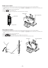
Traverse waveform
C (DC
voltage
)
0 V
Tracking servo
Sled servo
OFF
Tracking servo
Sled servo
ON
12. Press the [8] button on the remote control unit. (The tracking
servo and sledding servo are turned ON.) Confirm the C (DC
voltage) is almost equal to the A (DC voltage) is step 11.
13. Turn OFF the power, and remove the lead wire connected at
step 7.