


2 – Features of the CD-RW2000—Connections
14
TASCAM CD-RW2000
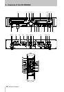
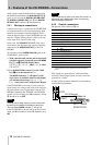
Audio signals output from the unit are output from
the balanced and unbalanced
ANALOG OUT
N
Q
jacks, as well as from the
DIGITAL AES/EBU OUT
W
,
DIGITAL COAXIAL OUT
jack
X
and
DIGITAL
OPTICAL OUT
connector
Y
simultaneously.
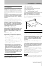
2.4.1 Word sync connections
It may be necessary to synchronize the CD-RW2000
to an external audio word clock when playing back
material. One example when this might be used is
when the digital outputs of the CD-RW2000 are con-
nected to a digital mixing console, which is serving
as the word clock source for the setup.
In this case, the WORD SYNC OUT of the word
clock master (the digital mixing console) should be
connected to the
WORD SYNC IN
V
of the CD-
RW2000.
To select the external
WORD SYNC IN
signal as the
CD-RW2000’s clock source:
1
With a disc inserted, and the unit in stop mode
(playback stopped), repeatedly press the
MENU
key (
9
or
6
) until the display shows
WORDSYNC>XXX
where
XXX
is either
ON
or
OFF
.
2
Use the
MULTI DIAL
control
B
or the
SKIP
keys
H
to set the function to
ON
.
The
WORD
indicator
7
will light if a valid
clock source is available, otherwise the display
will alternate the message
Word CLK
Err
(word clock error) with the time display.
If the CD-RW2000 is receiving a word clock sync
signal, and is also acting as the word clock source for
any units which receive digital audio from the CD-
RW2000 (remember that AES/EBU and IEC60958
signals are self-clocking), the
75
Ω
terminator switch
U
should be set to
OFF
.
NOTE
Entering record ready mode (or record mode) with
the word sync enabled will disable the word sync.
The front panel
WORD
indicator
7
will go out.
If the CD-RW2000 is the last unit in the word clock
chain, the
75
Ω
terminator switch
U
should be set to
ON
.
NOTE
There should be one, and only one, word clock source in a
digital audio setup. Multiple word clocks in a setup may
result in damage to equipment.
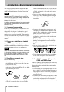
2.4.2 Control connections
The pinouts of this connector
T
are:
Tally signals are open collector, with a maximum
current of 50 mA. Input signals are active when low
(ground) for
≥
30 ms.
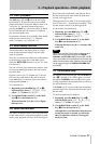
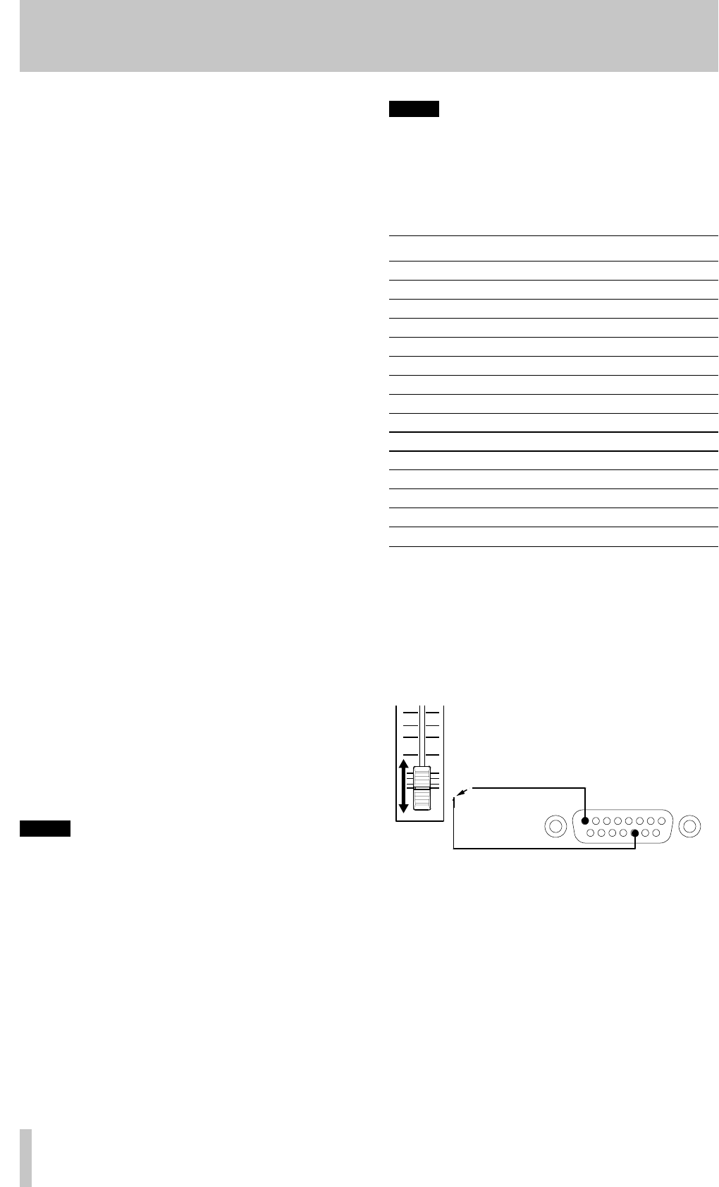
A fader start/stop control should be wired according
to the following schematic:
Pin Function
1STOP TALLY OUT
2 REC/PLAY TALLY OUT
3 SKIP (forward) IN
4 SKIP (back) IN
5 REC-PAUSE TALLY OUT
6 REC IN
7 Track increment IN
8GND
9PLAY TALLY OUT
10 PAUSE TALLY OUT
11 FADER START/STOP
12 STOP IN
13 PLAY IN
14 PAUSE IN
15
+5V
a
a.The maximum current supplied from this terminal is
50 mA.
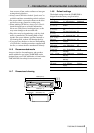
Pin 8 Ground
Pin 11 FADER
START/STOP
STOP
START
CONTROL I/O