


2 – Features of the CD-RW2000—Rear panel
12
TASCAM CD-RW2000
H
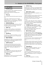
PLAY key
Use this key to start or resume playback or recording.
I
PAUSE key
Use this key to pause playback or recording.
J
RECORD key
Use this key to enter record ready mode (see 4,
“Recording” for details) and also to enter manual
track divisions (see 4.2.3, “Manual track division”).
K
SYNC REC key
Use this key to turn synchronized recording on and
off (see 4.3.1, “Synchronized recording” for details).
L
CALL key
Use this key for playback from the last pause position
before playback starts (see 3.4, “CALL playback” for
details).
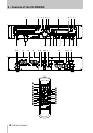
2.2 Rear panel
M
ANALOG INPUT (L, R)
(UNBALANCED)
These RCA jacks accept analog audio signals from
suitably-equipped units (–10 dBV, unbalanced).
N
ANALOG OUTPUT (L, R)
(UNBALANCED)
These RCA jacks output analog audio signals (at
–10 dBV levels, unbalanced) to suitably-equipped
units.
O
ANALOG INPUT (L, R) (BALANCED)
These XLR-type connectors accept analog audio sig-
nals from suitably-equipped units (+4 dBu,
balanced). The wiring, as described on the rear panel
of the unit is 1=ground, 2=hot, 3= cold.
P
ATT (attenuation for right balanced
analog output)
Use a small Phillips screwdriver with this attenuator
if you need to reduce the output signal level from the
right balanced analog output. As set at the factory, a
it is set to maximum output, and can reduce the level
by 20 dB.
Q
ANALOG OUTPUT (L, R)
(BALANCED)
These XLR-type connectors output analog audio sig-
nals to suitably-equipped units (+4 dBu, balanced).
The wiring, as described on the rear panel of the unit
is 1=ground, 2=hot, 3= cold.
R
ATT (attenuation for left balanced
analog output)
Use a small Phillips screwdriver with this attenuator
if you need to reduce the output signal level from the
left balanced analog output. As set at the factory, a it
is set to maximum output, and can reduce the level by
20 dB.
S
REMOTE IN (FROM RC-RW2000)
Use this connector with the cable from the supplied
RC-RW2000 remote control unit. Do not attempt to
use any other type of remote control unit with the
CD-RW2000.
T
CONTROL I/O
Use this 15-pin ‘D’-sub connector to connect the unit
to suitably-equipped equipment, allowing control of
the CD-RW2000. The pinouts of this connector are
given in 2.4.2, “Control connections”.
U
75
Ω
switch
This switch is used to turn the termination for the
WORD SYNC
input (
V
) on and off. See 2.4.1,
“Word sync connections” for details of word sync
operations.
V
WORD SYNC IN
This BNC connector is used to accept word synchro-
nization clock signals from other digital audio equip-
ment in a setup. A menu function is used to select the
source. See 2.4.1, “Word sync connections” for
details of word sync operations.
W
DIGITAL INPUT, OUTPUT (AES/EBU)
This pair of XLR-type connectors accepts (female)
and outputs (male) digital audio signals in AES3-
1992 format.
X
DIGITAL COAXIAL (IN, OUT)
These two RCA jacks accept and output digital audio
in standard IEC60958 Type II consumer format
(SPDIF).
Y
DIGITAL OPTICAL (IN, OUT)
These two TOSLINK optical connectors accept and
output digital audio in standard IEC60958 Type II
consumer format (SPDIF) using optical fiber
connectors.
Z
~ IN (AC power inlet)
Use the supplied power cable to connect the CD-
RW2000 to the AC power supply. Always ensure that
the voltage supplied is the same as that indicated on
the rear panel of the CD-RW2000. If you are in
doubt, consult a qualified electrician.