


54
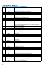
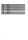
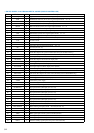
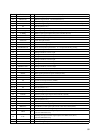
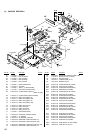
• DIGITAL BOARD IC102 MB90553ABPF-G-169-BND (DISPLAY CONTROLLER)
Pin No. Pin Name I/O Description
1
EQ O
EQUALIZER indicator (D123) drive signal output terminal “L”: on
2 SUR O
SURROUND indicator (D122) drive signal output terminal “L”: on
3 LEVEL O
LEVEL indicator (D119) drive signal output terminal “L”: on
4 NAME O
NAME indicator (D151) drive signal output terminal “L”: on
5 SETUP O
SET UP indicator (D152) drive signal output terminal “L”: on
6 VOLUME O
VOLUME indicator drive signal output terminal “L”: on Not used (open)
7 MUTING O
MUTING indicator (D101) drive signal output terminal “L”: on
8 JOG O
JOG indicator (D124) drive signal output terminal “L”: on
9 VOLUP O
Motor drive signal (volume up direction) output to the volume motor drive (IC105)
10 VOLDOWN O
Motor drive signal (volume down direction) output to the volume motor drive (IC105)
11 VSS —
Ground terminal
12 5V CHECK O
Power check terminal
13 POWER RY O
Power relay drive signal output terminal “H”: on
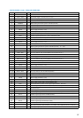
14 to 17 NC —
Not used (fixed at “L”)
18
SIRCS IN I
SIRCS input from the remote control receiver (IC101)
19
SOT0 O
Serial data output to the system controller (IC1201) (rewrite flash memory)
20
SIN0 I
Serial data input from the system controller (IC1201) (rewrite flash memory)
21
FL CLK O
Clock signal output to the fluorescent display tube
22
FL DATA O
Serial data output to the fluorescent display tube
23
VCC —
Power supply terminal (+5V)
24
FL LAT O
Latch signal output to the FL display driver (IC103)
25 FL CLEAR O
Clear signal output to the FL display driver (IC103)
26 OSD CLK O
OSD clock signal output to the select switch (IC2004) (used for STR-DE945 only)
27 C —
External power regulator capacitor is connected to this terminal
28 OSD DOUT O
OSD serial data output to the select switch (IC2004) (used for STR-DE945 only)
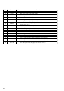
29 to 33
NC —
Not used (fixed at “L”)
34 AVCC —
Power supply terminal (+5V) (analog system)
35 AVRH —
Connected to power supply
36 AVRL —
Connected to ground
37 AVSS —
Ground terminal (analog system)
38
AD KEY IN 1 I
Key input terminal (A/D input) (S111 to 118)
39
AD KEY IN 2 I
Key input terminal (A/D input) (S121 to 125)
40
AD KEY IN 3 I
Key input terminal (A/D input) (S131 to 137)
41
AD KEY IN 4 I
Key input terminal (A/D input) (S141 to 149)
42
VSS —
Ground terminal
43
AD KEY IN 5 I
Key input terminal (A/D input) (S151 to 157)
44
AD KEY IN 6 I
Key input terminal (A/D input) (S161 to 165)
45
AD KEY IN 7 I
Key input terminal Not used (fixed at “L”)
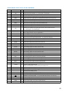
46
RDS SIGNAL I
RDS control signal input terminal Not used (fixed at “L”)
47
STOP I
Stop signal input from the power control (IC1206)
48
NC —
Not used (fixed at “L”)
49
MD0 I
MD 0 signal input from the system controller (IC1201)
50
MD1 I
MD 1 signal input terminal (fixed at “H” in this set)
51
MD2 I
MD 2 signal input from the system controller (IC1201)
52
HSTX I
Hardware standby signal input to the power control (IC1206)